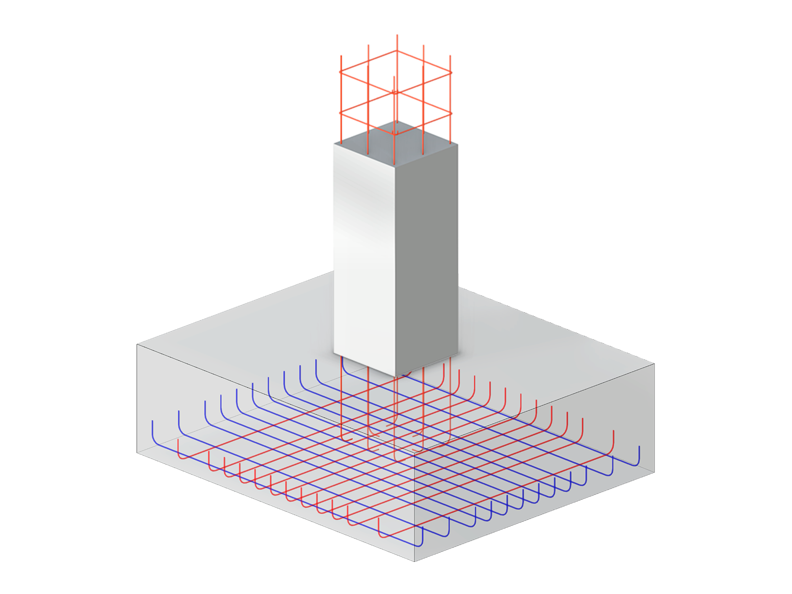
The eccentricity describes an imaginary distance from the center of gravity of a surface or a member to a real point in space. There is a difference between the following eccentricities:
Member Eccentricity
In RFEM and RSTAB, the member length corresponds to the distance between two nodes that is defined by the line of a member. In the case of cross-section connections or downstand beams, the reality is only modeled approximately. Using member eccentricities, it is possible to connect members eccentrically by specific member end sections. For example, this allows you to reduce design moments on horizontal beams for frames with large column sections. Member eccentricities are taken into account by transforming the degrees of freedom in the local element stiffness matrix.
Surface Eccentricity
The plane in the center of the surface represents the reference surface of the thickness. It is applied in equal proportions on both sides of this "central plane". By specifying the eccentricity ez, it is possible to arrange an offset of height for the surface. In this way, adjacent surfaces with different thicknesses are given a uniform top or bottom edge.
.png?mw=760&hash=177572a2e1120fc2a61cd35dce686890952ddb0d)


.png?mw=600&hash=49b6a289915d28aa461360f7308b092631b1446e)


