


Lösung für Laminat-, Sandwichtragwerke und Brettsperrholz (BSP)


Recommended Products for Laminate, Sandwich, and CLT Structures
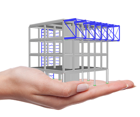
Definition of Multilayer Surfaces Such as Cross-Laminated Timber (CLT)

The Multilayer Surfaces add-on allows you to define multilayer surface structures. The calculation can be carried out with or without the shear coupling.

Construction Stages
The Construction Stages Analysis (CSA) add-on allows for considering the construction process of structures (member, surface, and solid structures) in RFEM.
Support and Learning
We provide professional support and many services in order to help you with finding a quick and efficient solution for your projects.


.png?mw=200&hash=ceabdac71454991b172d1a40faa3844b9a756ff1)

Palazzo Méridia in Nice, France
The recent trend in high-rise construction is clearly dominated by timber as the most ecological and environmentally friendly material. The project promoter Nexity is firmly committed to using constructive solutions with multiple labels and certifications in order to reduce carbon emissions and has therefore already built several commercial and office buildings using timber. These include Palazzo Meridia in Nice. This is currently the tallest CLT office building in France. The Dlubal customer CBS-Lifteam was responsible for the planning, supply, and installation of the timber structure.
-
Project Location
Nice, France
-
Software
RFEM 5 | Structural FEA Software

Wood Carving Workshop in Val Gardena, Italy
An extraordinary project was born when the architectural office of bergmeister-wolf designed a new workshop for wood carving art in Val Gardena, South Tyrol. As the triangulated facade could be used only partially for load application, the building represented a great challenge for the responsible timber construction engineer. However, the Dlubal customer Schrentewein & Partner mastered this task by primarily using the inner parts of the building for load transfer.
-
Project Location
Val Gardena, Italy
-
Software
RFEM 5 | Structural FEA Software
Nicht mehr aktuelle Produkte

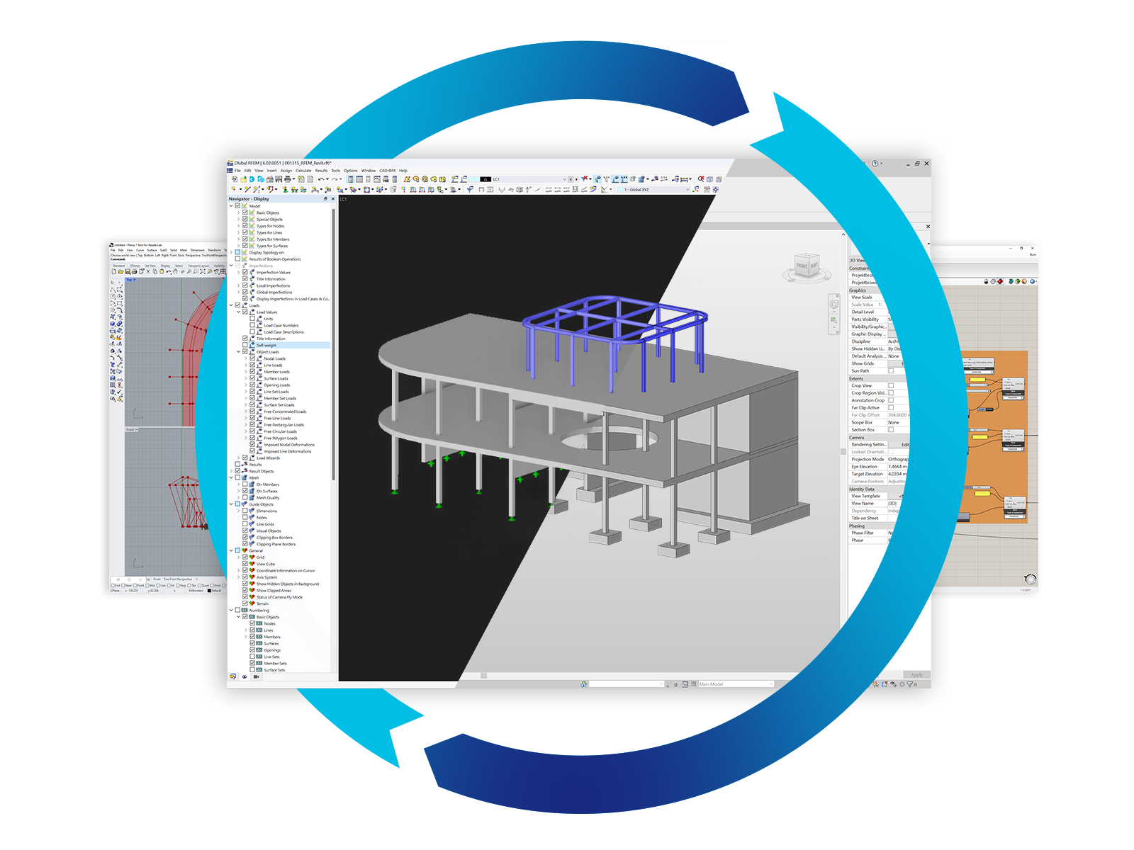
RFEM 5 | FEA Structural Analysis Software
The structural analysis program RFEM provides structural engineers with a 3D FEA program that meets all the requirements of modern civil engineering. Efficient data input and intuitive handling facilitate the modeling of simple and complex structures.
The add-on module for laminate, sandwich, and cross-laminated timber (CLT) structures in RFEM 5 is:
.png?mw=80&hash=24e105a767cf2e175614b729c2d2fa1673e4e81b)
Technical Support | Sales Team