


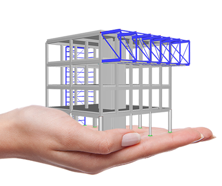
Solutions for Mechanical Engineering


Recommended Products for Mechanical Engineering


Support and Learning
We provide professional support and many services in order to help you with finding a quick and efficient solution for your projects.
After a thorough evaluation of the solutions available on the market, our choice naturally fell on RFEM by Dlubal for calculating our three-dimensional metal structures.
This software stands out for its compliance with Eurocodes, intuitive interface, and exceptional transparency in the display of input data and results. The technical service proved to be of high quality, combining patience, competence, and responsiveness, thus reinforcing our confidence in this choice.


.png?mw=200&hash=ceabdac71454991b172d1a40faa3844b9a756ff1)

Industrial Filter Device
The project for designing a filter/dryer device, including agitator, required a complete stress and deformation analysis in RFEM. What made the structure so special was its complex modeling with 1,424 surfaces, 158 solids, and 425 members.
-
Project Location
Germany
-
Software
RFEM 5 | Structural FEA Software

New Construction of Deep Drilling Rig
As the geothermal energy market is continuously increasing, the company BAUER Maschinen GmbH has developed a new deep drilling rig, which was used for the structural analysis performed by the Dlubal Software customer Ing.-Büro H.-U. Möller from Minden, Germany. The system can be used to drill to a depth of 7,000 m (22,965 ft) in the areas of geothermal energy, oil, or gas.
-
Project Location
Germany
-
Software
RSTAB 8 | Structural Frame & Truss Analysis Software
Outdated Products

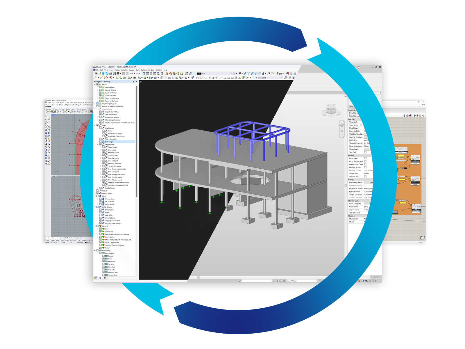
RFEM 5 | FEA Structural Analysis Software
The structural analysis program RFEM provides structural engineers with a 3D FEA program that meets all the requirements of modern civil engineering. Efficient data input and intuitive handling facilitate the modeling of simple and complex structures.
.png?mw=80&hash=24e105a767cf2e175614b729c2d2fa1673e4e81b)
Technical Support | Sales Team