


Questions about structural engineering? Mia answers immediately!


.png?mw=1024&hash=aeb4eef06592d784fa1f0dfcb514e59fd45bcb79)
Dlubal_KohlA_]_LI.jpg?mw=400&hash=b19f0b64f31f0dfc292e91d388ff4ead0b408e47)
Main Program RFEM or RSTAB


Extension Products for Structural Engineering
Hybrid Timber Construction with Complementary Materials
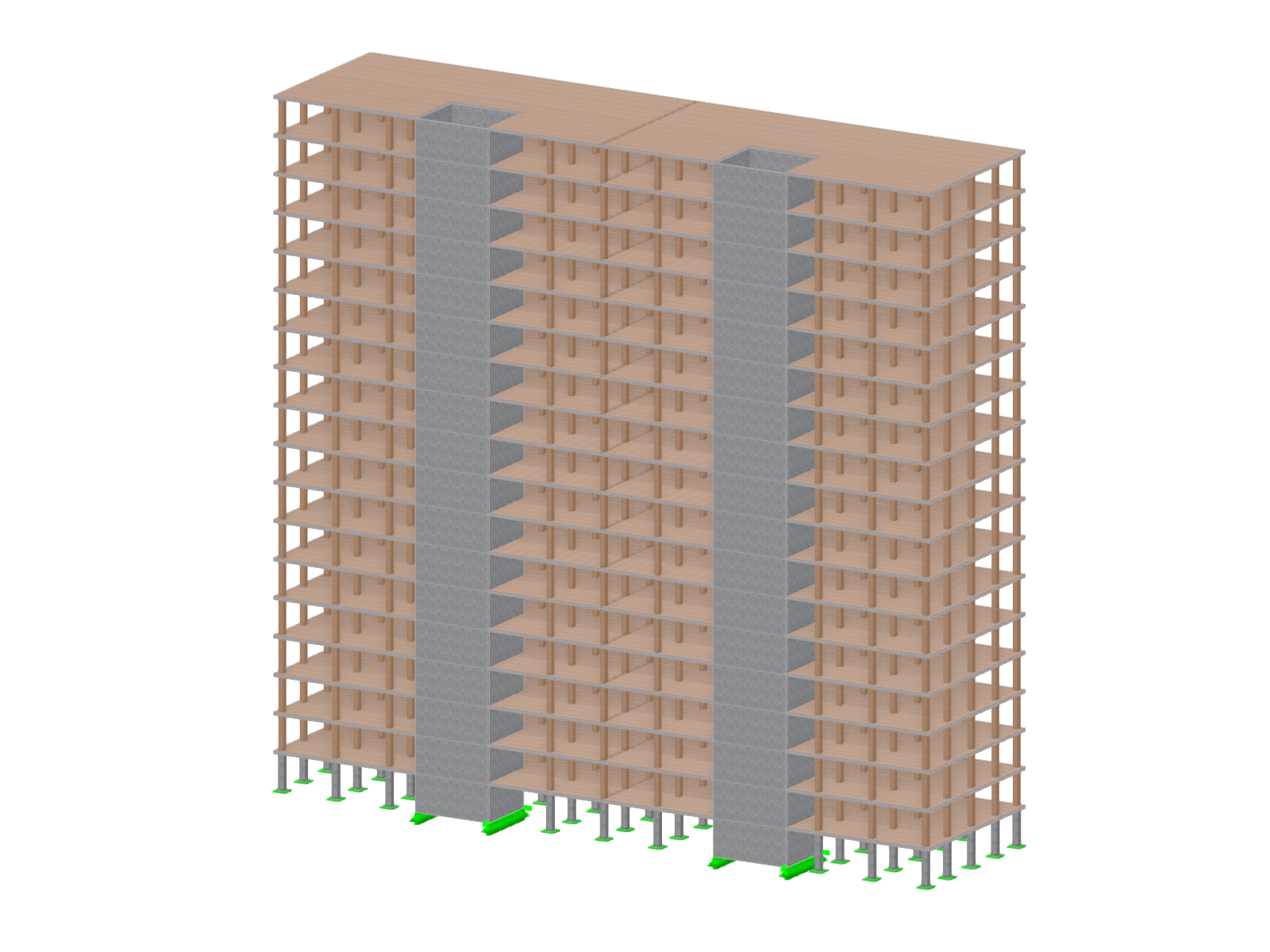
The "Building Model" add-on simplifies the modeling and analysis of timber buildings. It speeds up the creation of building models and automatizes the load generation, ideal for demanding structural timber projects.
Geotechnical Analysis
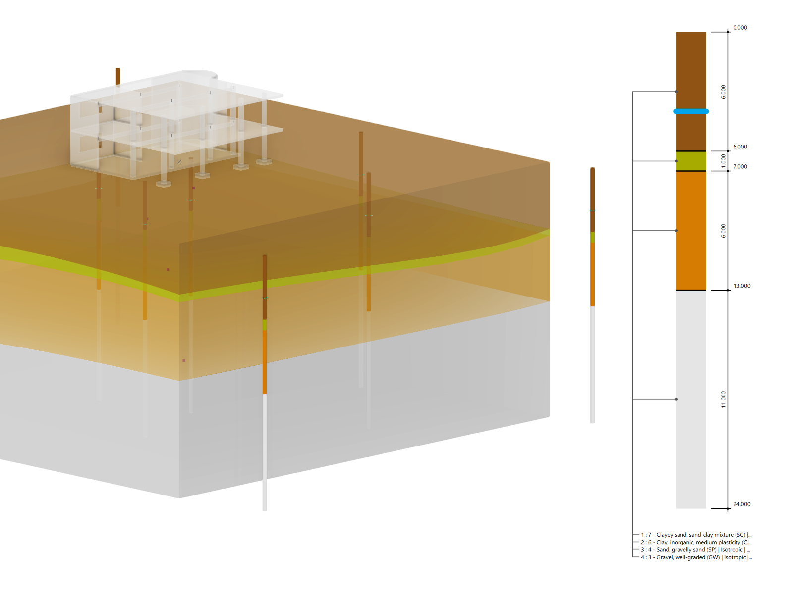
In RFEM, the Geotechnical Analysis add-on uses the properties from soil samples to determine a soil body to be analyzed.
Construction Stages
The Construction Stages Analysis (CSA) add-on allows for considering the construction process of structures (member, surface, and solid structures) in RFEM.
Time-Dependent Analysis (TDA)

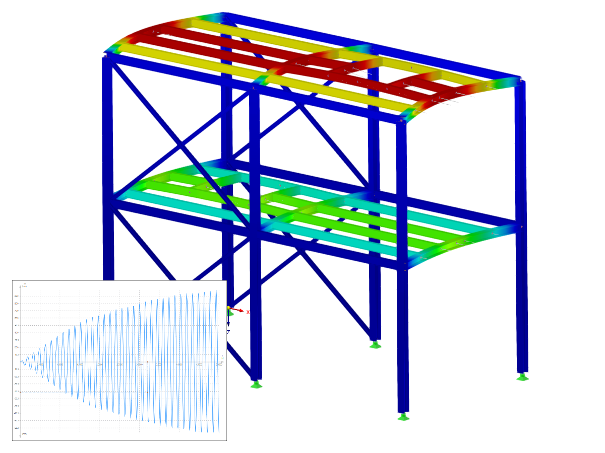
The Time-Dependent Analysis (TDA) add-on allows you to consider the time-dependent material behavior of members and surfaces. The long-term effects, such as creep, shrinkage, and aging, can influence the distribution of internal forces, depending on the structure.

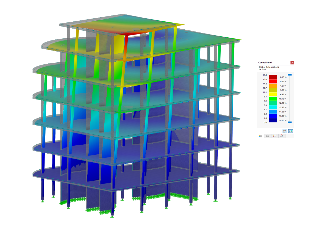
Response Spectrum Analysis
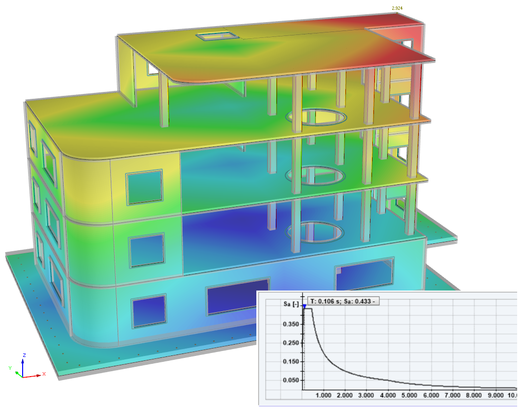
The Response Spectrum Analysis add-on performs seismic analysis using multi-modal response spectrum analysis. The spectra required for this can be created in compliance with the standards or can be user-defined. The equivalent static forces are generated from them. The add-on includes an extensive library of accelerograms from seismic zones that can be used to generate the response spectra.

Definition of Multilayer Surfaces Such as Cross-Laminated Timber (CLT)

The Multilayer Surfaces add-on allows you to define multilayer surface structures. The calculation can be carried out with or without the shear coupling.


.png?mw=600&hash=49b6a289915d28aa461360f7308b092631b1446e)


Support and Learning
We provide professional support and many services in order to help you with finding a quick and efficient solution for your projects.


.png?mw=200&hash=ceabdac71454991b172d1a40faa3844b9a756ff1)

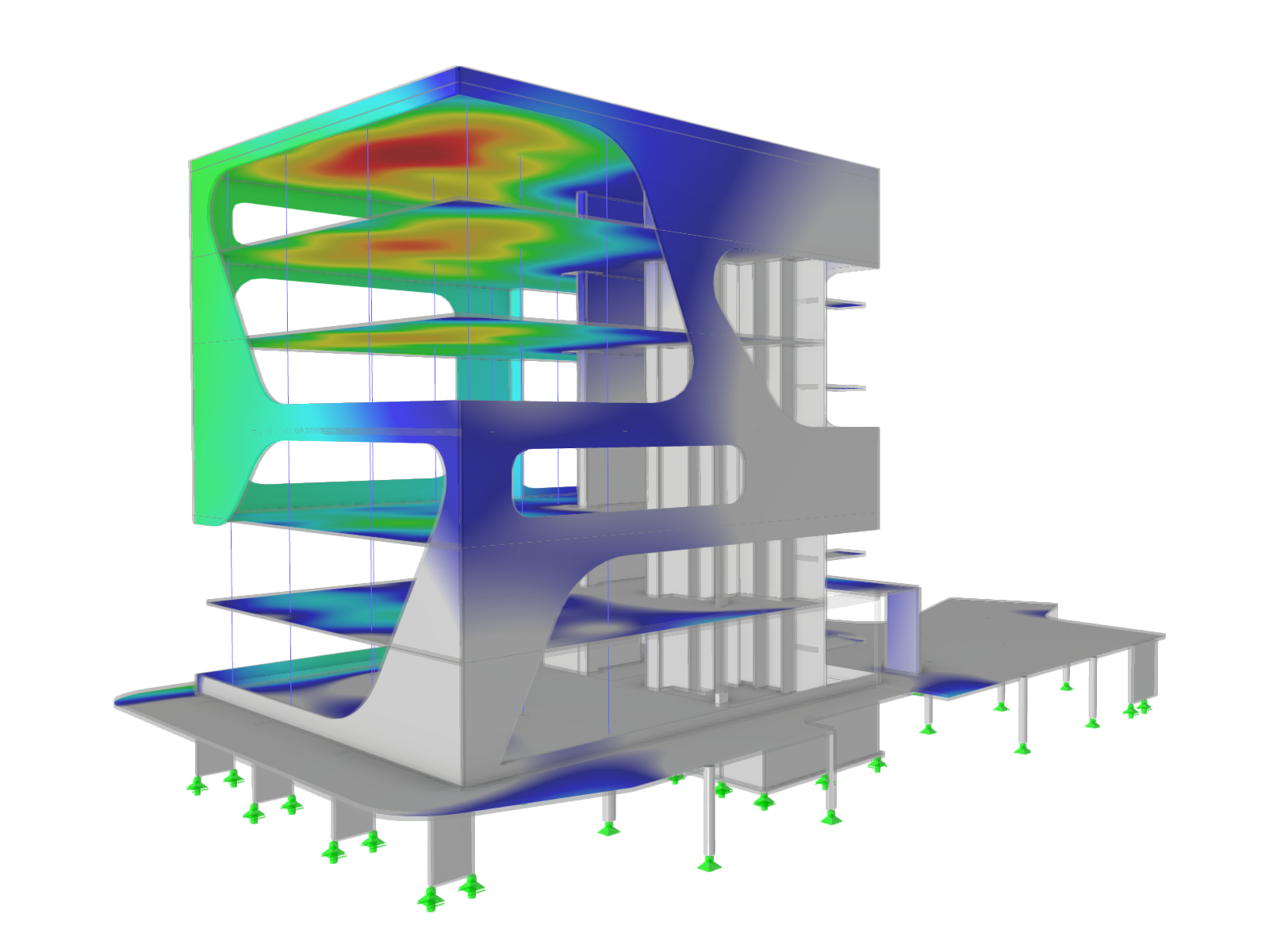
Construction of Jo&Joe Hotel Building in Gentilly, France
This project represents a major technical challenge for the company Le Bras Frères, of which the new team embodies an internal generational shift highlighted by a significant desire to increase skills and productivity through new investments (acquisition of a size K2i machine, extension of production facilities, and so on).
-
Project Location
89-93 avenue Paul Vaillant Couturier | Gentilly | France
-
Software
RFEM, RF-LAMINATE, RF-TIMBER Pro, RF-STEEL EC3
.png?mw=80&hash=24e105a767cf2e175614b729c2d2fa1673e4e81b)
Technical Support | Sales Team