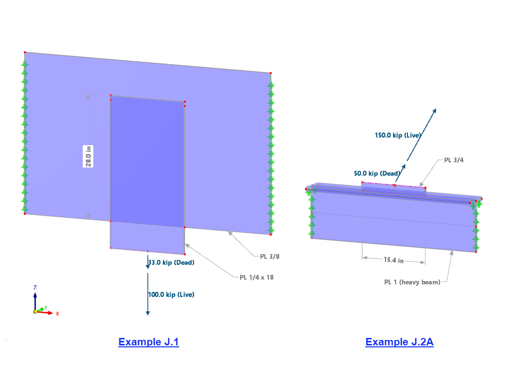
AISC Example J.1 Fillet Weld in Longitudinal Shear
As shown above in Image 01, a ¼-inch-thick plate is welded to a 3/8-inch-thick plate. The plates are ASTM A572 Grade 50. Weld: 70 ksi electrodes, 3/16-inch leg size, 27 inches long.
Several joint types are available, including butt joint, corner joint, lap joint, and tee joint. For the first example, lap joint and single fillet are selected (Image 02). The weld arrangement controls whether the weld is arranged on the bottom or the top of the connected surface. An error message appears to suggest reversing the orientation if the initial selection is incorrect. For the weld size, enter the throat thickness of 3/16 inch x 0.707 = 0.13256 inch. First select the line for the weld, then the two surfaces that need to be connected. The weld length is equal to the total length of the selected line(s).
Under the Stress-Strain Analysis folder, the default Line Welded Joint Configuration can be edited (Image 03). Deactivate the irrelevant stress types.
The limit stress may be calculated according to AISC Equation J2-4 (excluding the weld area) for LRFD design. This value is then compared to the resulting stress, σ|j+s+w|.
|
φ |
LRFD resistance factor |
|
β |
Reduction factor = 1.2 - 0.002(27.0-in/0.1875-in) ≤ 1.0 |
|
Fnw |
Nominal stress of the weld metal, ksi |
|
kds |
Directional strength increase factor (1.0 for longitudinal direction) |
The "Special Options" (Image 04) provide the ability to redistribute the local stress peaks over the length of the weld. Select "Constant" for the shear and normal loads. For the bending loads, select "None" to ignore the unwanted moment in the resulting stress.
The available stress analysis methods, Simplified and Directional, are according to EN 1993-1-8 [3]. Select the "Simplified" method for this example.
After running the calculation, select Stresses in Line Welds from the drop-down menu to view the stress result (Image 05). The stress ratio from the AISC example is equal to 200 kips/206 kips = 0.971. This is comparable to the stress ratio of 1.0 in RFEM.
AISC Example J.2A Fillet Weld Loaded at Angle
In this second example, a 3/4-inch-thick gusset plate is welded to the top of the beam flange (1.0-inch-thick flange and web are assumed in the model). The loads are applied at a 60° angle relative to the weld longitudinal axis. The plates are ASTM A572 Grade 50. Weld: 70 ksi electrodes, 5/16 inch leg size, 15.4 inches long (Image 01).
Similar to the workflow shown above, create a new Line Welded Joint. Select Tee Joint and Double Fillet (Image 06). For the weld size, enter a throat thickness of 5/16 inch x 0.707 = 0.221 inch.
A new Line Welded Joint Configuration needs to be added, since a different limit stress is used in this example.
The directional strength increase factor according to AISC Equation J2-5 may be used to increase the limit stress for a fillet weld loaded at an angle.
|
kds |
Directional strength increase factor |
|
θ |
Angle between the line of applied force and the weld longitudinal axis, degrees |
Limit stress according to AISC Equation J2-4 (excluding the weld area) for LRFD design:
|
φ |
LRFD resistance factor |
|
Fnw |
Nominal stress of the weld metal, ksi |
|
kds |
Direction strength increase factor |
The stress ratio of 1.0 in RFEM verified the required length calculated in the AISC example. In addition to stress, the internal forces can also be displayed graphically. The total shear stress W may be multiplied by the weld length to verify the total applied load (Image 07).
It should be noted that additional AISC requirements for fillet welds must also be checked. This includes minimum and maximum sizes, minimum length, effective length, and other limitations covered in AISC Section J2.2b.


.png?mw=350&hash=c6c25b135ffd26af9cd48d77813d2ba5853f936c)


Dlubal_KohlA_]_LI.jpg?mw=350&hash=5e0bf8d59d91aaa767fa193a08a18d93cb2175d5)
weiske-partner.de__LI.jpg?mw=350&hash=a54864f43592f5dfd5afd06514a2e812555d4579)


.png?mw=512&hash=4a84cbc5b1eacf1afb4217e8e43c5cb50ed8d827)




_1.jpg?mw=350&hash=ab2086621f4e50c8c8fb8f3c211a22bc246e0552)


.png?mw=600&hash=49b6a289915d28aa461360f7308b092631b1446e)


