


Questions? Mia answers immediately!


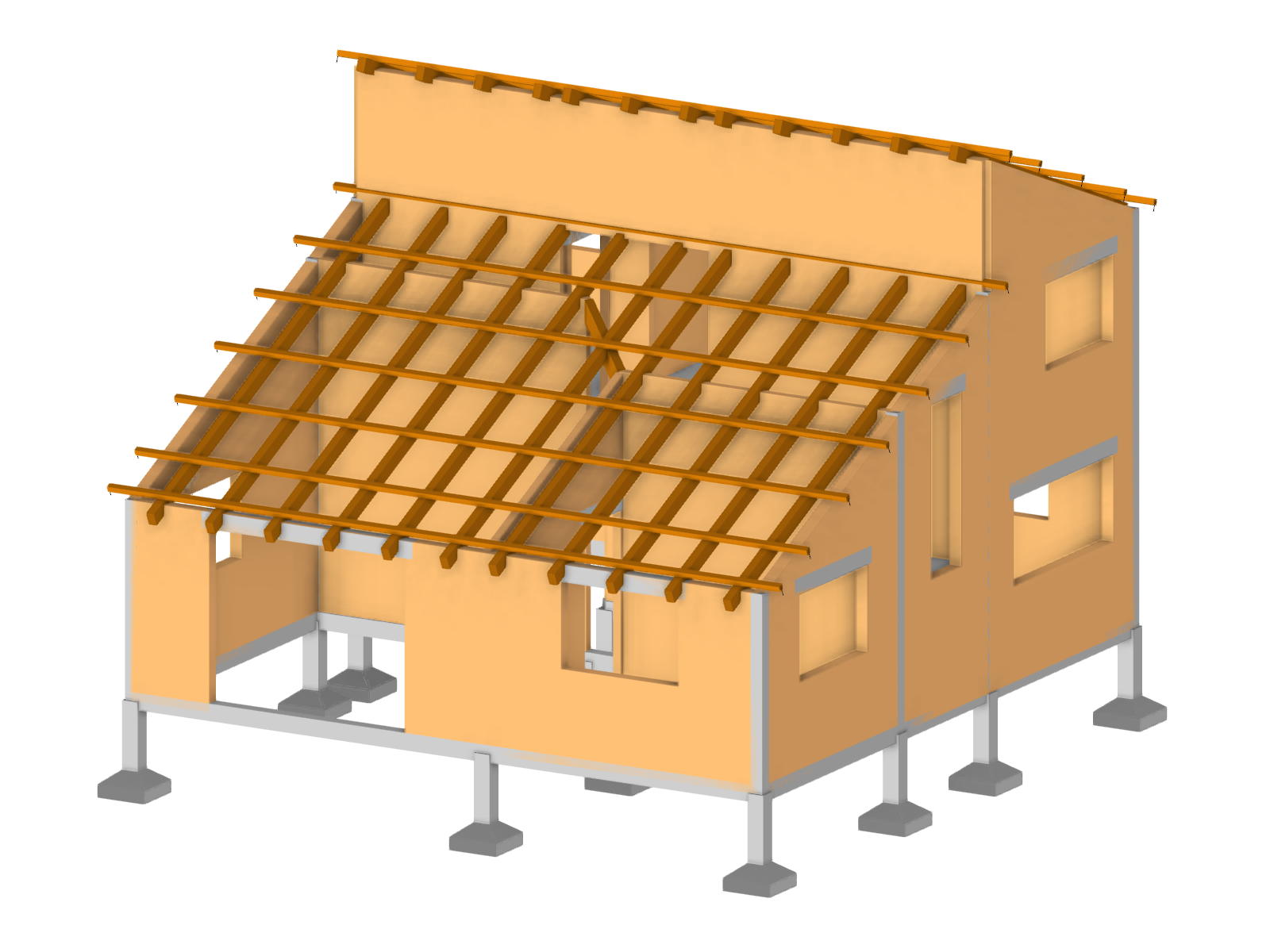
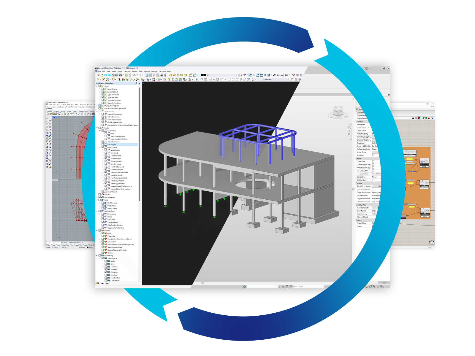
Structural Models | Masonry Structures
.png?mw=400&hash=28f0d9e2c5b8fd3cf99a02e133a57397a437ea44)
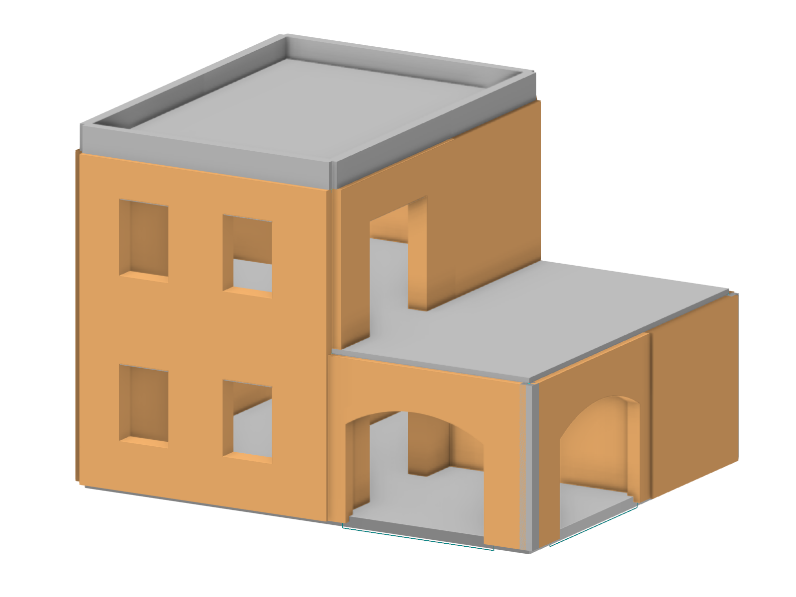
Solutions for Masonry Structures


Recommended Add-on Products for Masonry Structures

Geotechnical Analysis
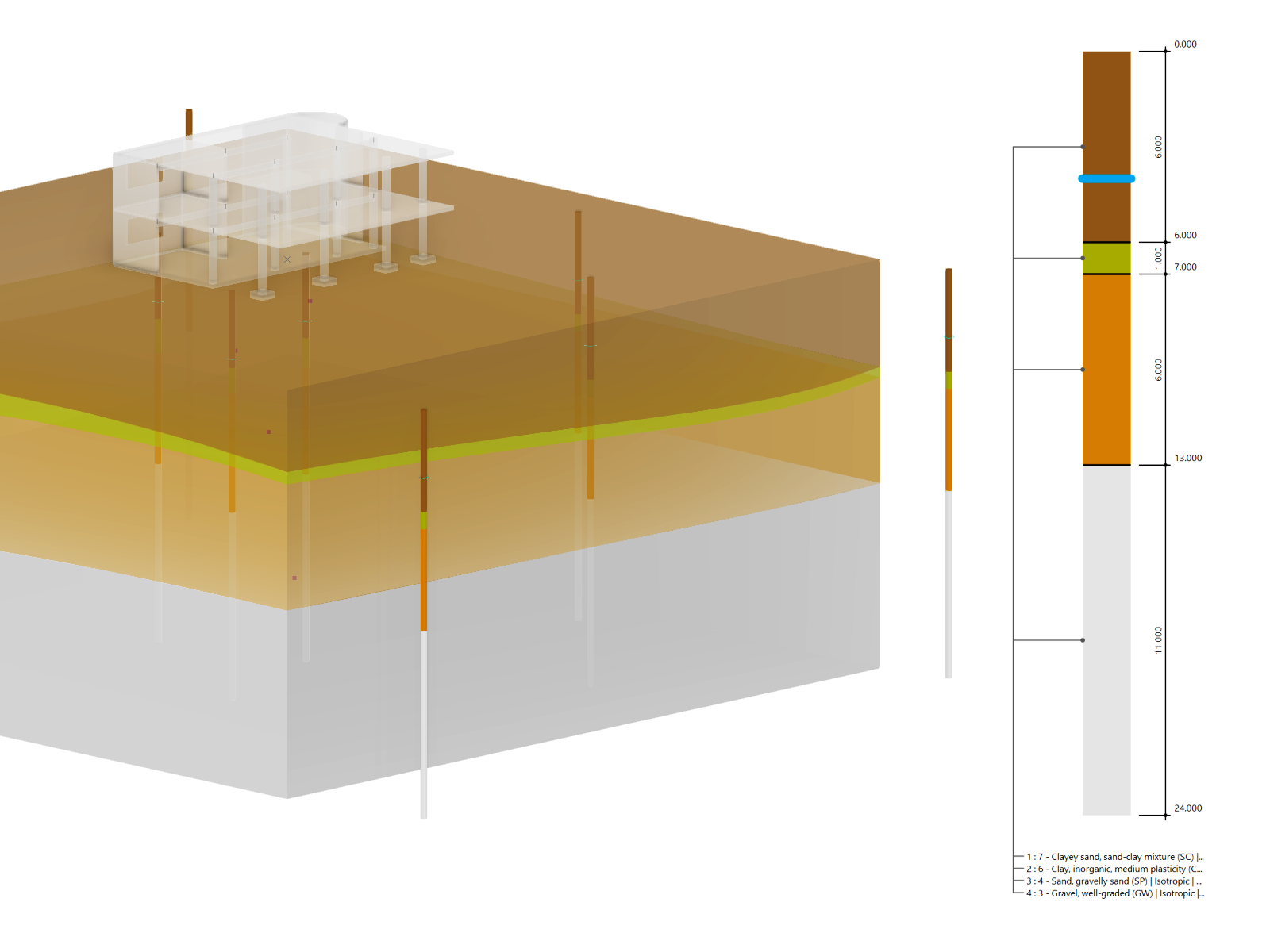
In RFEM, the Geotechnical Analysis add-on uses the properties from soil samples to determine a soil body to be analyzed.
Construction Stages
The Construction Stages Analysis (CSA) add-on allows for considering the construction process of structures (member, surface, and solid structures) in RFEM.
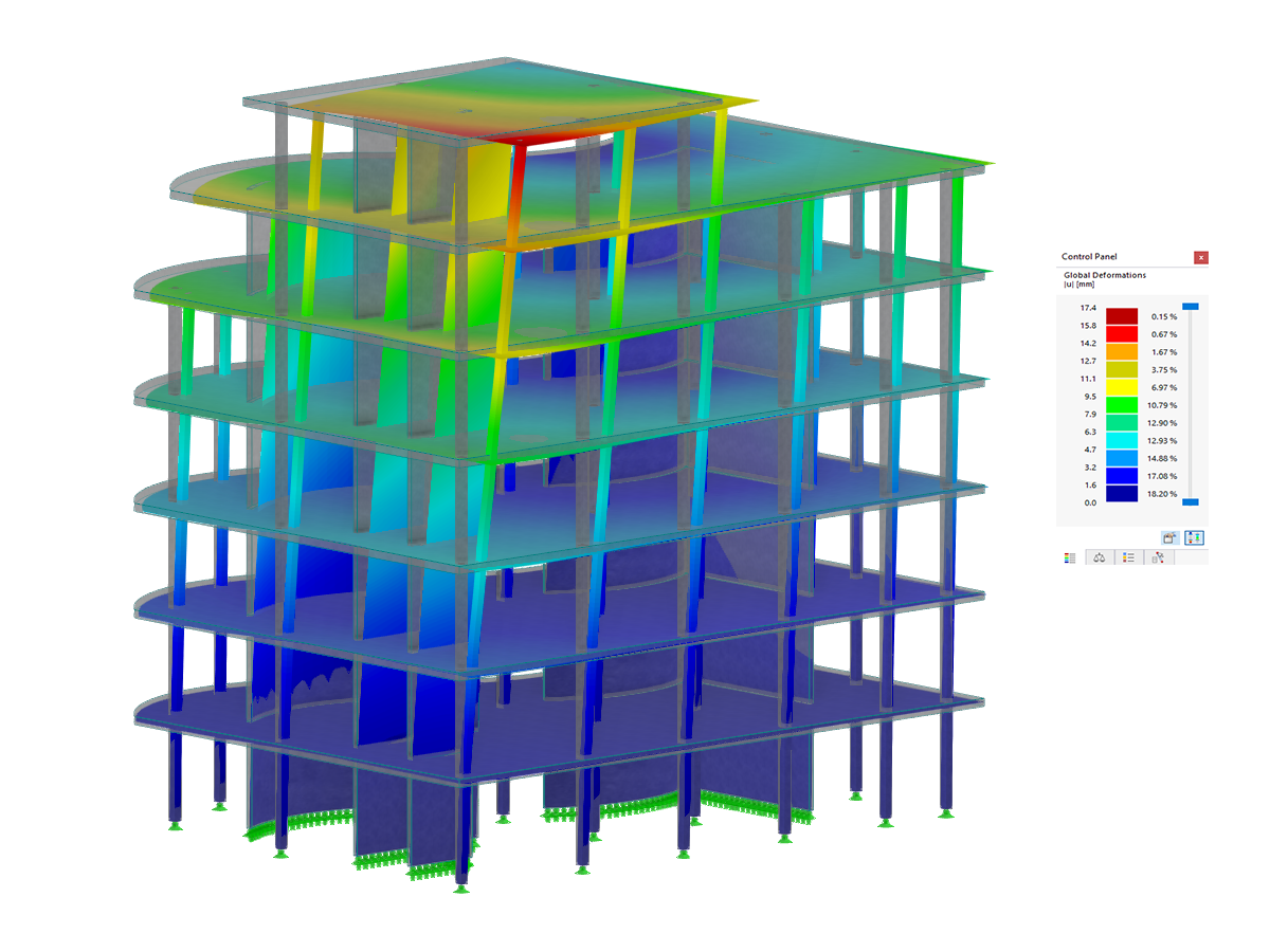
Response Spectrum Analysis
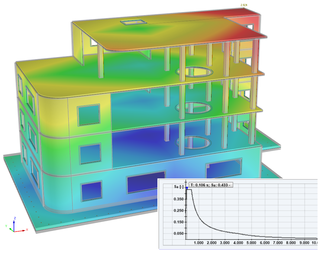
The Response Spectrum Analysis add-on performs seismic analysis using multi-modal response spectrum analysis. The spectra required for this can be created in compliance with the standards or can be user-defined. The equivalent static forces are generated from them. The add-on includes an extensive library of accelerograms from seismic zones that can be used to generate the response spectra.

Support and Learning
We provide professional support and many services in order to help you with finding a quick and efficient solution for your projects.


.png?mw=200&hash=ceabdac71454991b172d1a40faa3844b9a756ff1)

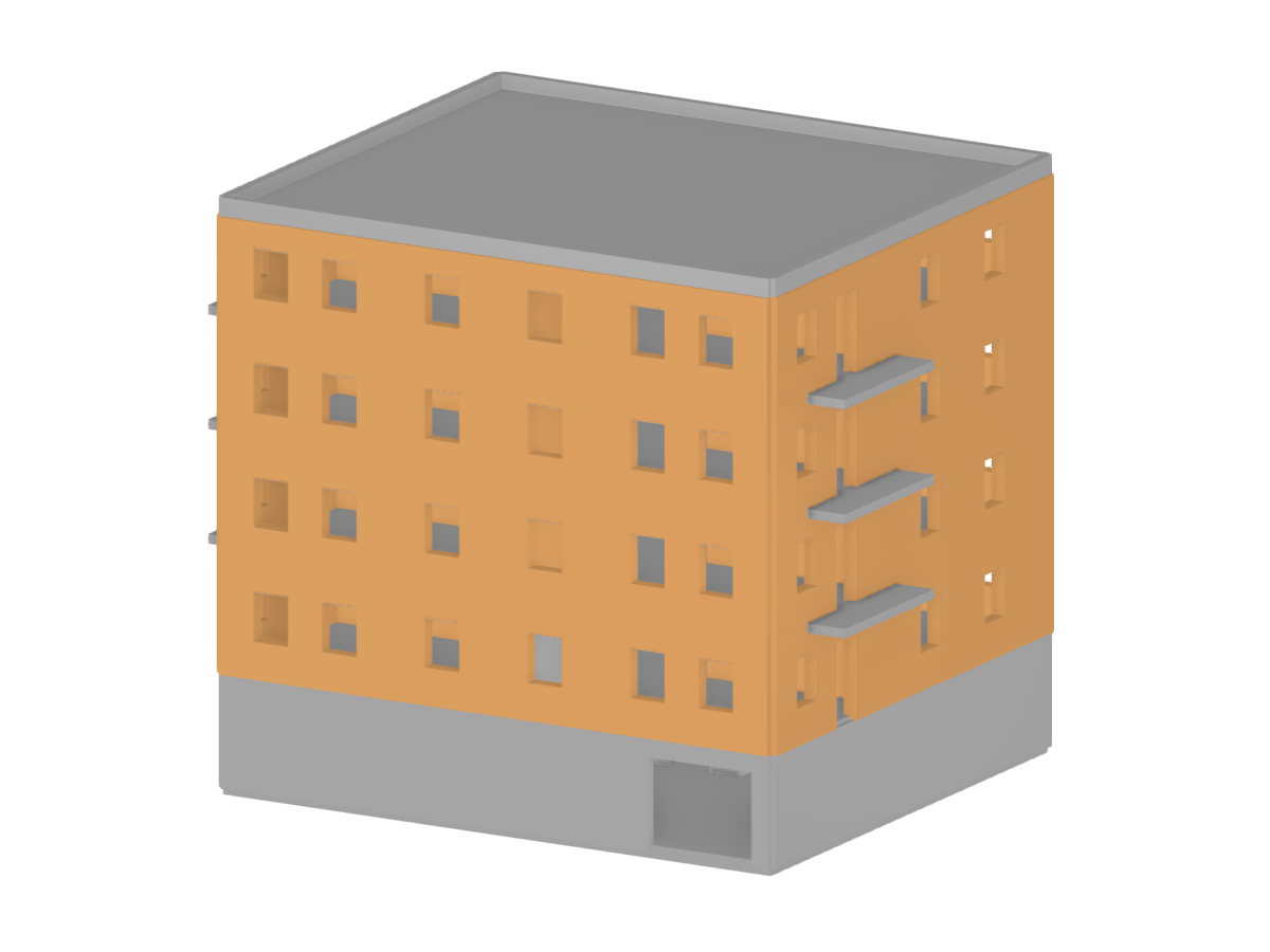
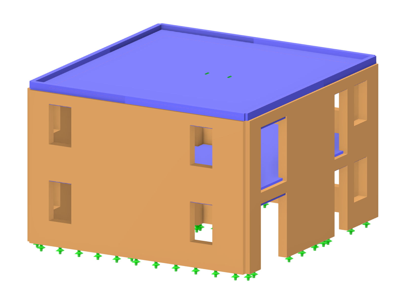
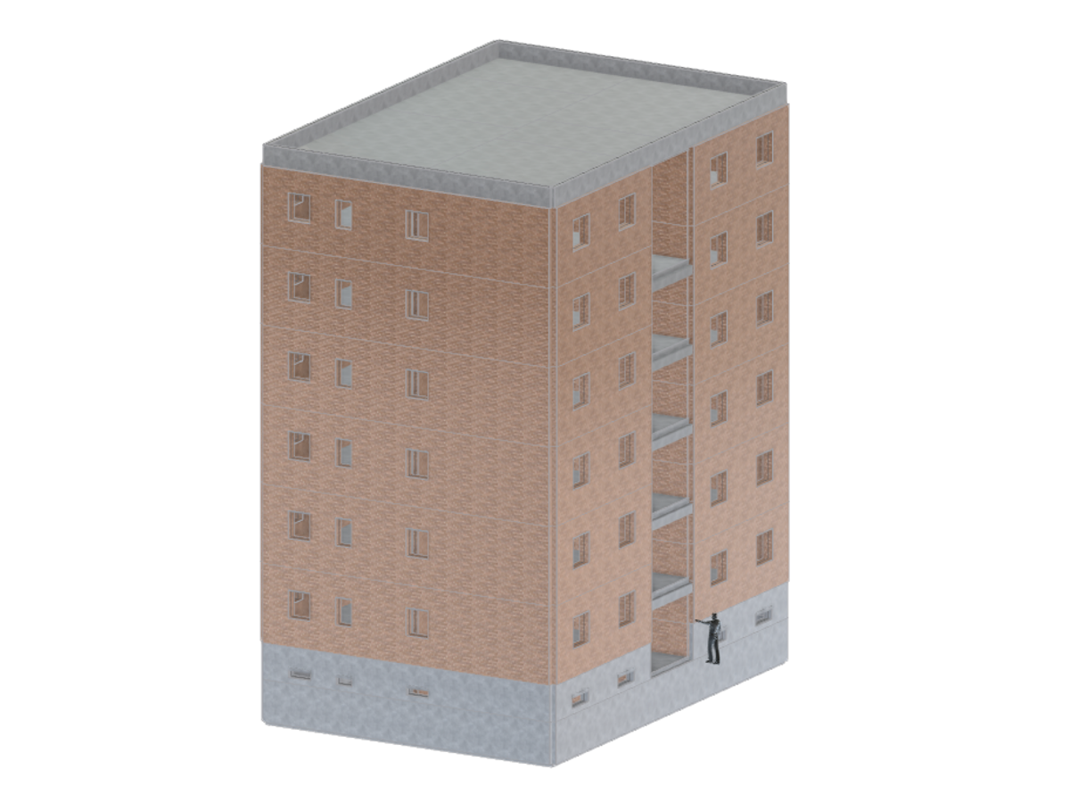
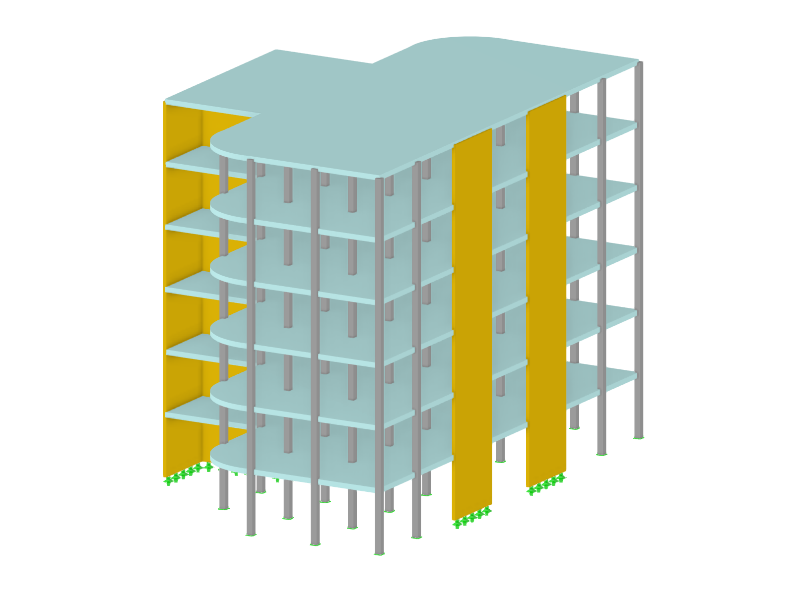
Residential Building in Los Mochis, Sinaloa, Mexico
The structure consists of one-way concrete slabs supported by reinforced concrete columns and beams. The masonry is designed structurally, and the entire structure is founded on a nonlinear elastic support in the seismic zone.
-
Project Location
Sinaloa, Mexico
-
Software
RFEM 5

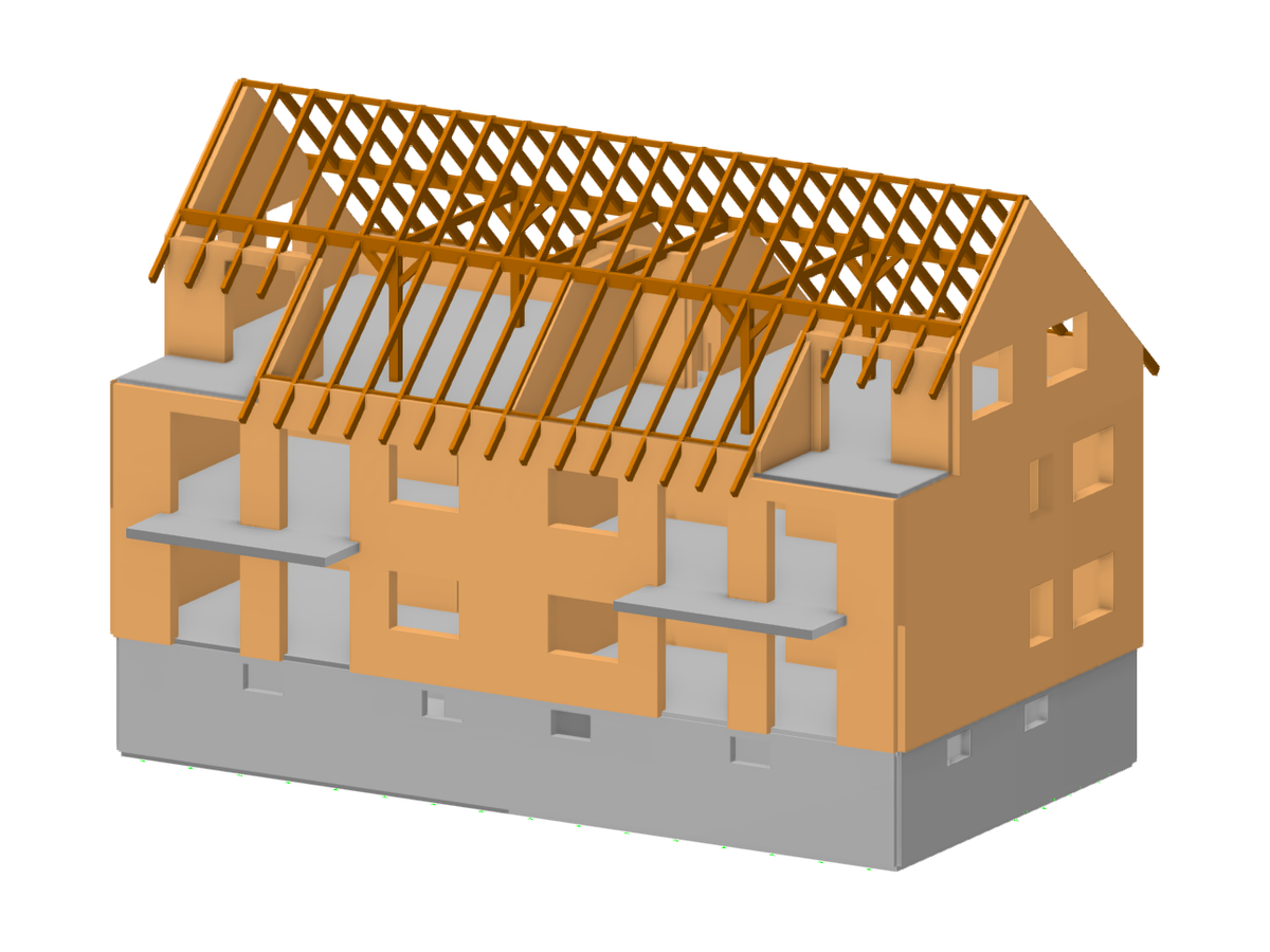
Kappl Village Center, Austria
Local materials such as natural stone masonry and larch wood were used in the construction. The upper green roof additionally forms a harmonious and flowing transition to the north-facing slope.
-
Project Location
Tyrol, Austria
-
Software
RFEM 5

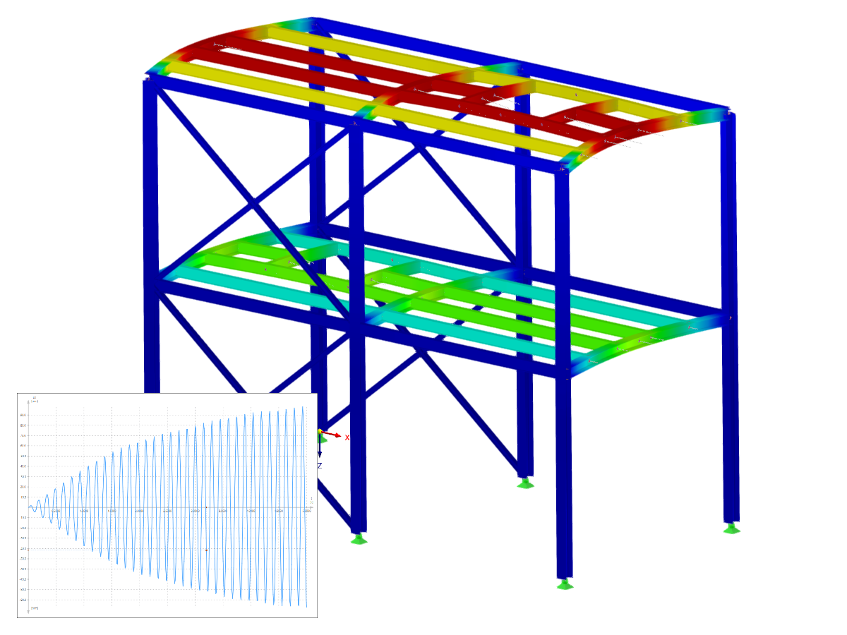
Revitalization and Extension of Supporting Structure of Stage Roof in State Playhouse Dresden, Germany
The total height of the stage tower is about 38 m (125 ft), measured from the stage floor to the top of the roof. The primary structure of the roof consists of five steel trusses arranged parallel to each other. The top chord nodes of the outer truss girder are partially braced on the existing walls by inclined members.
-
Project Location
Dresden, Germany
-
Software
RSTAB 8
.png?mw=80&hash=24e105a767cf2e175614b729c2d2fa1673e4e81b)
Technical Support | Sales Team