Visibilities provide options to display model cutouts or specific components. You can not only graphically define the model, load, or guide objects contained in a visibility, but select them according to various criteria in 'Navigator - Views'.
Defining a visibility graphically via menu or buttons
To create a model section, select the relevant objects first. You can use different selecting functions, for example, by drawing a window, or use the object selection according to specific settings (see the Selection Options chapter).
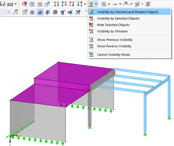
Then, the "Selection" list button provides various options to use the current selection for a visibility.
The same functions are available with the Visibility entry on the View menu. They have the following meaning:
- Visibility by Selected and Related Objects: The selected objects are displayed, including their definition objects. For example, if you have selected a line, its nodes are also included in the section.
- Visibility by Selected Objects: Only the selected objects are displayed. The section shows the selected line without nodes.
- Hide Selected Objects: The selected objects are taken out of the display.
- Visibility by Window: The visibility is created graphically by drawing a window. If you draw the window from left to right, it includes only the objects that are completely within the window area. When opening the window from right to left, all objects that are cut by the window are also part of the visibility.
- Show Previous Visibility: The last active visibility is redisplayed ("Undo" function).
- Show Reverse Visibility: When using this visibility, the current display is reversed. The hidden objects appear as a new visibility.
- Cancel Visibility Mode: The visibility mode is closed and all objects are displayed again.
Transparency for hidden objects
In a visibility, the hidden objects are displayed with minor intensity. You can adjust the degree of transparency in the "Settings" tab of the "Program Options & Settings" dialog box. This dialog box can be accessed via the Options menu or the
![]() button in the menu bar.
button in the menu bar.
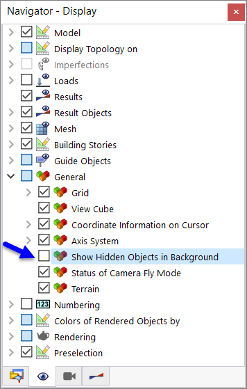
If you want to hide the inactive objects completely, deactivate the corresponding check box in the 'Navigator - Display'.
Defining a visibility in the navigator
Visibilities can also be created according to certain criteria that must be fulfilled for the objects. You can use visibilities generated by the program as well as user-defined object selections. The visibilities are managed in Navigator - Views.
Generated Visibilities
RFEM automatically creates visibilities for model objects such as lines, members, and surfaces according to certain criteria. They provide a quick overview of the model. You can filter the objects using the list; thus you have the possibility to check the entered data. The visibilities are also useful for evaluating results.
In addition to the multiple criteria selection (default setting), it is possible to create intersecting sets. You can control these settings with the
![]() and
and
![]() buttons at the end of the list (see the Table below).
buttons at the end of the list (see the Table below).
Visibilities from object selection
All 'OS' object selections that you have created (see the Object Selections chapter) are available in the list. This allows you to show and hide model objects, imperfections, loads, and guide objects that meet certain criteria.
The buttons below the Visibilities list have the following functions:
|
|
Opens the New Object Selection dialog box to define a new OS |
|
|
Opens the New Object Selection dialog box to adjust the selected OS |
|
|
Adds object selected in work window to object selection to be defined in a dialog box |
|
|
Removes object selected in work window from object selection to be defined in a dialog box |
|
|
Activates all object selections in list |
|
|
Reverses selection of object selections |
|
|
Applies sum of criteria selected for visibility |
|
|
Applies intersecting set of criteria selected for visibility |
|
|
Controls whether definition objects belonging to objects are also displayed |


.png?mw=350&hash=e3f5898d72f463e9b3e774659aabcb220466c522)