For each nodal release, it is necessary to specify the properties that control the transfer of deformations (and thus of internal forces and moments) between the original node and its copy. This nodal release type describes the properties of the hinge on the invisible member between the two nodes.
Coordinate System
The release of the displacements and rotations can be related to one of the following axis systems:
- Local member or line axis system x,y,z
- Global coordinate system X,Y,Z
- User-defined axis system U,V,W
If a local member or line axis system is used, enter the number of the corresponding object in the Local Axis System dialog section.
Release Type Conditions
The release type conditions are divided into "Translational" and "Rotational" degrees of freedom. The former describe the displacements in the direction of the local or global axes; the latter describe the rotations about these axes.
To define a release, select the check box for the respective axis. The check mark indicates that an object's displacement in or rotation about the corresponding direction is possible. Then, the constant of the translational or rotational spring is set to zero. You can adjust the "Spring constant" anytime in order to model an elastic hinge. Enter the spring stiffnesses as design values.
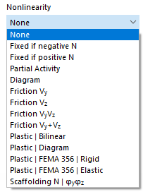
In the "Nonlinearity" column, you can specifically control the release for each deformation component. Depending on the degree of freedom, appropriate entries are available for selection in the list of nonlinearities.
The nonlinearities are described in the chapter Member Hinges .
Local Axis System
This dialog section is displayed if the release refers to a local coordinate system. Use the list to define whether a "Member" or a "Line" serves as a reference. Then, enter the number of the member or line. You can also use the
![]() button to define the object graphically.
button to define the object graphically.

