The Moving Load wizard facilitates the task of applying moving loads to surfaces or members. In addition to concentrated loads, you can use load models consisting of several loads that gradually move across the model. Practical areas of application are crane loads and vehicle loads for bridge structures. The program creates corresponding load cases from the load positions of the moving load.
Main
In the Main tab, you define the geometric specifications for the moving load, such as the object, direction of movement, and moving step between load positions.
Generate on
Select from the list the objects on which the generation of loads is to be performed:
- On surfaces
- On members
The input parameters are adjusted to this specification.
If the load only moves over certain surfaces or members, deactivate the "All" check box. You can then enter the numbers of the relevant objects or select them graphically on the model using the
![]() button.
button.
Trajectory Definition
In this section, you can define the topology of the moving loads: The "Line Set" (for surfaces) or "Member" or "Member Set" (for members) specifies the way in which the loads move over the surfaces or members.
A line set contains one or more lines that describe the direction in which the load moves. It is therefore advantageous if the RFEM model already contains a "guiding line" for the loads. If no line set has been defined yet, use the
![]() button to create a line set. This opens the dialog box
Newr Line Set
.
button to create a line set. This opens the dialog box
Newr Line Set
.
You can use the
![]() button to edit the current line set and the
button to edit the current line set and the
![]() button to select another line set graphically on the model.
button to select another line set graphically on the model.
With parallel loads, for example, you can arrange the line set in the middle and then carry out the lane definition with the appropriate eccentricities.
Lane Definition
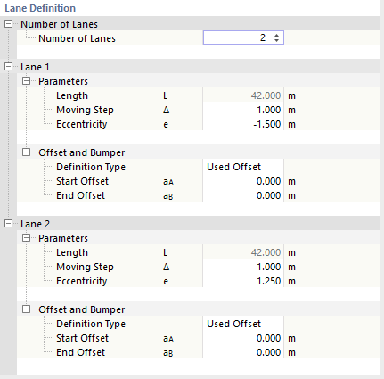
This section manages the number of parallel lanes, the increment of the load positions, as well as the distances of the moving load from the line set or from the line start and end.
Number of Lanes
For moving loads on surfaces, specify how many lanes are parallel to the continuous line. A category is added for each additional lane.
Lanes – Parameters
The "Length" L of the line set or member / member set is displayed for information purposes.
Enter the "Moving Step" Δ: It controls the (equal) distances at which the loads move over the surfaces or members. The smaller the moving step, the more load cases are created.
The "Eccentricity" e makes it possible to arrange loads on surfaces next to the moving line. This allows you to use the boundary lines of a surface as a reference, for example, without having to define new lines. The moving loads then move at a lateral distance parallel to the lines of the line set. The following applies to the sign convention: The direction of the set of lines is specified by the sequence of lines. A positive eccentricity arranges the loads to the left of the moving line in the viewing direction, a negative eccentricity to the right.
Lane Offset and Bumpers
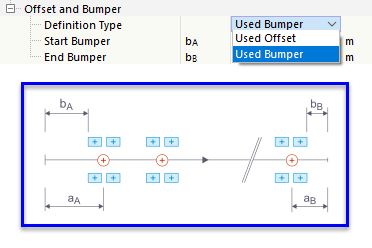
Load generation starts at the start node of the first line in the line set or the first member in a member set. It ends at the end node of the last line or the last member. You can use the parameters of this category to shift the start point and end point of the moving load. In the list, select whether there is an "Offset" or a "Bumper".
- Offset: The start offset aA describes the distance of the first load position from the start node of the line or member set, the end offset aB describes the distance of the last load position from the end according to the sketch.
- Bumper: You can use the start bumper bA and the end bumper bB to define areas at the start and end of the line or member set that remain free of loads. Bumpers are relevant for crane runway girders and structures with lateral boundaries. Load models with negative x-locations, for example, are then shifted until they no longer extend into the start bumper.
Movements
In the Movements tab, you can assign the appropriate load models to the lanes.
The load wizard uses what are referred to as "Sets of Movements". They allow you to control which load combinations move in specific lanes.
Lane Definition
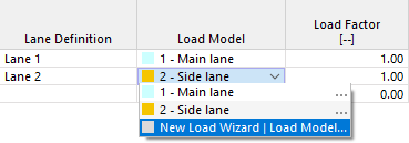
In the list, select one of the lanes that you have created and provided with parameters in the "Main" tab during the lane definition. If the loads move in parallel in several lanes, you can specify the next lanes in the other rows.
Load Model
In the second column, you can enter the moving load composition that moves along the lane. The list allows for a selection from among the load compositions defined as load models.
You can use the "..." option to edit a load model and the "New Load Wizard | Load Model" entry to create a new load composition.
Load Factor
You can scale the effect of the individual load models with factors.
Distance
This column is accessible when you re-select a lane for load assignment. It makes it possible to apply a load composition to the same line or member set with an offset, for example when dual-axis load models move across the surface or member in succession.
The load distance from the fixed point of the previous load position must be specified as a positive value.
Independent Steps
This column is also only accessible if a lane appears several times (see image above). The check box is not selected by default. This means that the other load model moves synchronously with the first along the lane.
If this option is activated, the two load compositions move independently of each other over the surfaces or members – both individually and together. For the combinations, the distance defined in the previous column is taken into account as the minimum distance between the load positions. A large number of load cases can occur as a result.
Load Cases
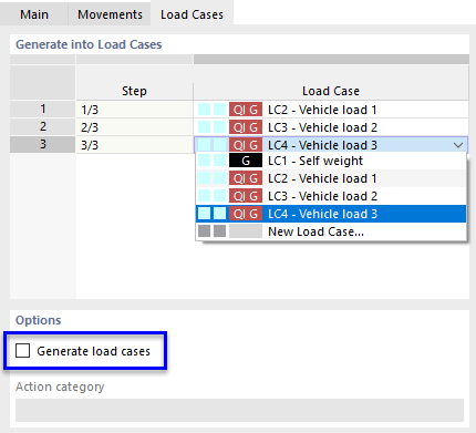
The Load Cases tab lists the load steps with the load cases that result from the topology and load parameters.
Generate into Load Cases
The "Step" column provides information about the number of load positions. For each step, a load case is created to which the designation ML (Moving Load) is assigned along with the load step. During the generation process, the next free load case numbers are used or gaps in the numbering are filled.
Options
The "Generate load cases" check box is selected by default. This means that the load cases are created automatically. If you clear the check box, these load cases are deleted. You can then assign the load positions individually to specific load cases. You can create new load cases using the "New Load Case" option in the list.
The appropriate action category must be assigned to the generated load cases. It controls which partial safety factors and combination coefficients are applied when the load cases are superimposed.
Click OK to transfer the generated load cases to RFEM and close the load wizard.


