Visual objects are 3D objects such as people, cars, trees, or textures. They are often used for realistic representations in architecture software. In RFEM, you can integrate 3D objects into the model in order to illustrate proportions.
Categories
Set the 'File Name' by using the
![]() button to select the file in the Windows dialog. The visual object can have one of the following formats:
button to select the file in the Windows dialog. The visual object can have one of the following formats:
- *.3ds (3D Studio file)
- *.stl (stereolithography file)
- *.obj (Wavefront file)
Define the coordinate system to which the 3D object refers. You can select a user-defined coordinate system from the list or use the
![]() button.
button.
The 'Rotation sequence' describes the order of angles by which a rotation of axes can be performed.
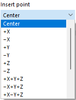
The 'Insert point' determines which location on the “3D box” of the visual object is placed at the origin point. Various options are available for selection in the list:
Origin Point
Enter the position of the visual object in the model, or define the location graphically with the
![]() button. The center of the visual object is related to it.
button. The center of the visual object is related to it.
Options
If you want to use a 'Non-uniform scale' for scaling the object in the spatial directions, activate the check box. Thus, the corresponding text boxes in the "Scale" section become accessible.
Scale
In this dialog section, you can adjust the size of the visual object to the proportions of the model. The normal case is a "Uniform scale" Δ with regular scaling in all directions. For a non-uniform scale, activate the corresponding check box in the "Options" section.
You can use the
![]() button to switch between relative and absolute input.
button to switch between relative and absolute input.


