In the Settings & Options tab, you can adjust the value for the acceleration of gravity, the geometric tolerances of objects, and the alignment of axes.

Settings
This dialog section manages the value of the "Acceleration of gravity" g. It is used for determining the self-weight of members and surfaces, the conversion of masses, and dynamic analyses. The approximate value of 10.00 m/s² is preset.
Model Tolerances
When modeling or importing data from a CAD program, slight geometric differences may occur in the model objects. RFEM corrects these inconsistencies automatically if particular distances are exceeded. Thus, nodes located very close to each other will be combined, lines or members located outside of planes will be integrated into surfaces, or minimally inclined lines and members will be classified as vertical.
The preset tolerances are suitable for most models. In the case of small model dimensions, it may be necessary to adjust the tolerances accordingly.
Options
The options in this section control whether "representatives" for members and sets of members or "surface cells" are used in the model.
If activating the check boxes for "Member Representatives" and "Member Set Representatives", the additional tabs Member Representative Wizard and Member Set Representative Wizard are available in the dialog box. If you select the "Surface Cells" check box, the program automatically detects closed partial areas of surfaces. This object type is described in the chapter Surface Cells.
Global Axes XYZ
This dialog section controls the orientation of the global axis Z. The Z-axis is usually directed upwards in CAD programs, and downwards in structural analysis programs. This is irrelevant to the calculation.
If Z is directed upwards, the factor −1.0 is automatically applied in Z for the "Active self-weight" function in the load case (see the chapter Load Cases ).
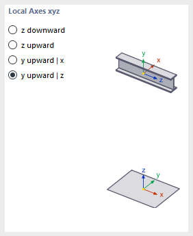
Local Axes xyz
The descriptions of the member axes are regulated differently in the standards. In this dialog section, you can define how the principal member axes z or y, as well as the surface axis z, are oriented in order to adapt the local axis systems to the regional conventions.
The positions of the local member and surface axes are illustrated in the dialog graphics.