


Line welded joints are required for a stress analysis of welds. If you define a weld for a line in a surface model, the stresses of this weld are generated using the Stress-Strain Analysis add-on. Thus, you directly obtain the stresses for the weld design for the selected weld type.

Main
In the Main tab, you define the weld type and set its parameters.
Categories
In this dialog section, specify which weld is present. The types, including parameters, are displayed in the dialog graphic.
Joint Type
The following joint types are available for selection in the list:
- Butt Joint
- Corner Joint
- Lap Joint
- Tee Joint
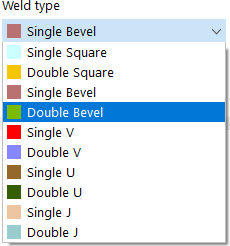
Weld Type
Depending on the joint type, the list offers different options to perform weld design checks.
Weld Arrangement
The list provides two options for arranging the weld axis system:
- Reverse Surface Normal (-z)
- Surface Normal (+z)
This allows you to control whether the weld is arranged on the bottom (+z) or on the top (−z) of the connected surface. For symmetrical weld types such as a T-joint with double fillet weld, the arrangement is irrelevant.
Longitudinal Arrangement
Line welded joints can be arranged to be "Continuous" or "Intermittent" along the line length. In the latter case, the longitudinal dimensions of the weld segments and the interruptions and, if applicable, the distance of the first weld segment from the start of the line must be specified.
Parameters
In this dialog section, enter the "Weld size" to define the weld thickness. The "Weld length" is taken from the line length.
Assigned to Line No. and Surfaces No.
Define the line and the surface on which you want to arrange the weld. You can use the
![]() button to define the objects graphically.
button to define the objects graphically.
Only surfaces with one of the following material types can have line welds assigned to them:
- Base
- Steel
- Metal
- Aluminum
