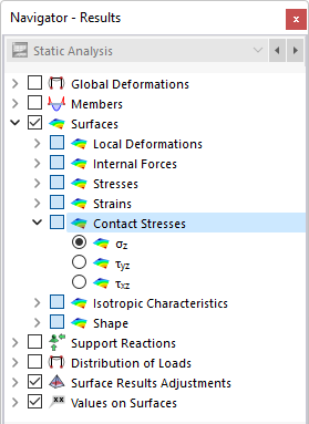
For surfaces provided with a Surface Support, you can display the 'Contact Stresses' in the navigator and table. The table lists the contact stresses of each surface according to the specifications set in the Result Table Manager .
The contact stresses have the following meanings:
| Fz | Contact force in the FE node in the direction z |
| A | Application area for the FE node |
| Fy | Contact force in the FE node in the direction y |
| A | Application area for the FE node |
| Fx | Contact force in the FE node in the direction x |
| A | Application area for the FE node |
The table lists the stresses as force per unit area that are introduced into the surface support. Thus, with regard to signs, the table does not show the reaction forces or moments on the part of the support. The signs result from the direction of the global axes. If the local surface axis z is directed downwards, the "Self-Weight" load case, for example, results in a positive stress σz. Thus, the signs result from the direction of the local surface axis z.
Sum of loads and sum of support forces
For load cases and load combinations, the check sums Σ of loading and support forces are indicated at the end of the table. This balance will show a difference if the model also has nodal supports, line supports, or member supports. Those support forces must also be considered in the overall balance.

