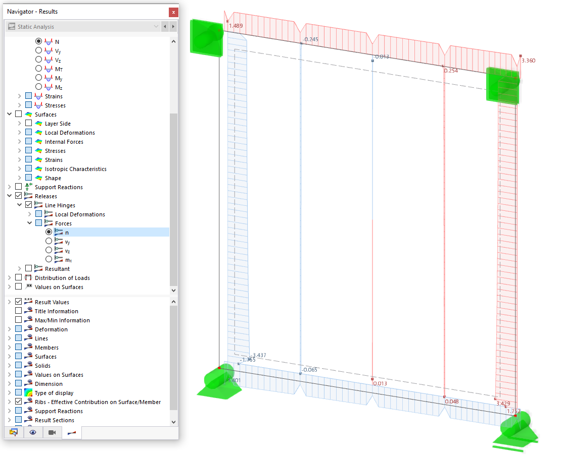
In the "Navigator - Results", specify the design results of the reinforcement sections that should be displayed graphically on the members. You can select specific results for the required reinforcement, provided reinforcement, and not covered reinforcement.
The cross-sectional area of the selected reinforcement type is displayed for each member location. You can see the position of the reinforcement – above or below – by means of the display on the corresponding member sides.
Control Panel
If you select several reinforcements, the reinforcement cross-sections are displayed in combination. The color assignments are shown in the control panel. This way, you can graphically compare the required longitudinal reinforcement with the provided longitudinal reinforcement, for example.
The not covered reinforcement represents the difference between the provided and required reinforcement.
Result Display
The "Members" category in the lower navigator area provides you with various options for adapting the result display (see the image Comparing Required and Provided Reinforcement). You can display the distribution of the reinforcement with or without hatching, show all values of the design locations, or only show the extreme value of all members.






.png?mw=512&hash=4e74affa9ad0c7b703151c5085ac9b8e59171c23)


