


Considering Shrinkage
Shrinkage describes a time-dependent change of volume without the effect of external loads or temperature. This manual will not go into details regarding shrinkage problems and their individual types (drying shrinkage, autogenous shrinkage, plastic shrinkage, and carbonation shrinkage).
Significant influence values of shrinkage are relative humidity, effective thickness of structural components, aggregate, concrete strength, water-cement ratio, temperature, as well as the type and duration of curing. The shrinkage-determining value is the total shrinkage strain εcs at the considered point of time t.
According to EN 1992-1-1, Section 3.1.4, ([2] Eq. (3.8)), the total shrinkage strain εcs is composed of the components for drying shrinkage εcd and autogenous shrinkage εca, as summarized in the equation below.
Drying Shrinkage
The component from drying shrinkage εcd is determined according to [2] Eq. (3.9) as follows.
where
-
t
Age of concrete at relevant point of time in days
ts
Age of concrete when shrinkage starts in days
h0
Effective thickness of the structural component [mm] (for surfaces: h0 = h)
kh
Coefficient according to [1], Table 3.3, depending on the effective cross-section thickness h0
εcd,0
Basic value according to [1] Table 3.2, or Annex B, Eq. (B.11)
-
Ac
Cross-sectional area
u
Cross-section perimeter
-
αds1, αds2
Factors for considering the type of cement
fcm
Mean cylinder compressive strength of concrete in [N/mm²]
fcmo
= 10 N/mm²
| Cement |
|
|
|
|
|---|---|---|---|---|
| 32,5 N |
|
|
|
|
| 32.5 R; 42.5 R |
|
|
|
|
| 42.5 R; 52.5 N/R |
|
|
|
|
Autogenous Shrinkage Strain
The autogenous shrinkage strain εca is determined according to [2] Eq. (3.11) as follows.
where
Considering Shrinkage in Concrete Design (Taking Reinforcement into Account)
Specifications for the shrinkage strain are entered in the material dialog box in the Time-Dependent Properties of Concrete section. The age of concrete at the considered time and at the start of shrinkage, the relative humidity, and the cement type must be specified here. Based on these specifications, the program determines the shrinkage strain εcs.
The shrinkage strain εcs (t,ts) can also be specified manually, independent of standards.
The shrinkage strain is only applied to the concrete layers; the reinforcement layers remain unconsidered. There is, therefore, a difference compared to the classical temperature loading, which also affects the reinforcement layers. Thus, the model for shrinkage used in the program considers the restraint of the shrinkage strain εsh that is exerted by the reinforcement or the cross-section curvature for an unsymmetrical reinforcement. The resulting loads from the shrinkage strain are automatically applied to the surfaces as virtual loads and calculated. Depending on the structural system, the shrinkage strain results in additional stresses (statically indeterminate system) or additional deformations (statically determinate system). Therefore, the program considers the influence of the structural boundary conditions in different ways for the shrinkage.
The shrinkage depends on the correct distribution of the stiffness in the cross-section. It is, therefore, recommended to take tension stiffening and a small value for damping into account for the tension areas of the concrete.
The 1D model in the image below illustrates how shrinkage is considered in the program.
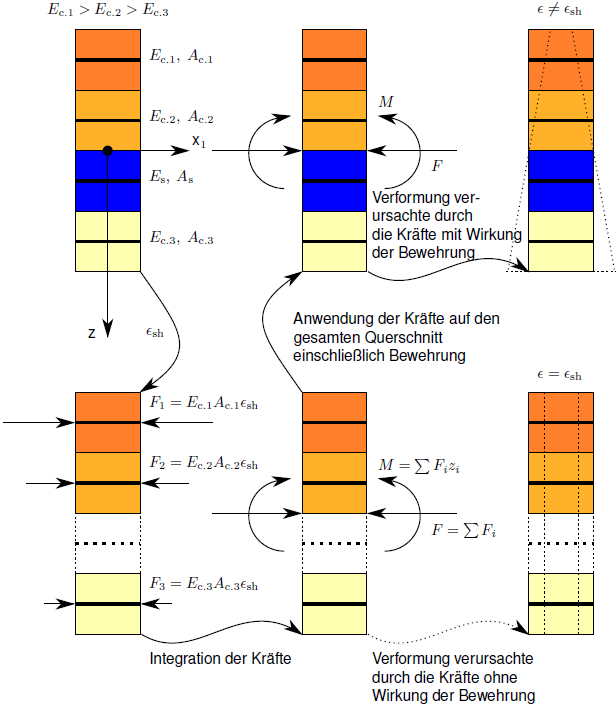
As a simplification, four layers are considered:
- The dark orange layers represent the concrete with little damage,
- the light orange layers represent the more heavily damaged concrete.
- The blue layer corresponds to the reinforcement.
- Each concrete layer is characterized by the actual modulus of elasticity Ec,i and each cross-sectional area by Ac,i.
- The reinforcement is characterized by the actual modulus of elasticity Es and the cross-sectional area As.
- Each layer is described by means of the coordinate zi.