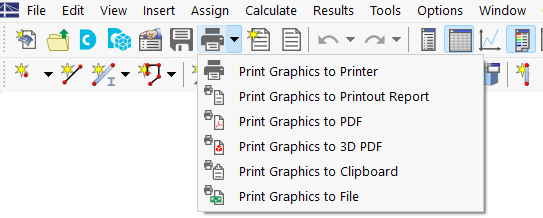
The Concrete Design add-on is completely integrated in RFEM or RSTAB. Therefore, you can use all options known from the main program to document the graphical results of the design ratios and reinforcements. The general procedure of preparing graphics for printout is described in Chapter Graphics of the RFEM manual.
Graphics of Work Window
Chapter Graphics for Concrete Design presents all result types that are graphically available for members, surfaces, and nodes. You can print the current view directly using the print function, or transfer it to the printout report.
In the '"Graphic Printout" dialog box, specify the print settings for the image as usual.
If you activate the Multi Print option in the 'Window' category, you can define the specifications for printing several windows or the mass print of graphics in the "Add-ons" tab (see Chapter Using Multi Print of the RFEM manual). The graphics are then sorted in the printout report with the Concrete Design results.
Design Details and Result Diagrams
The dialog boxes of Design Details, Result Diagrams in Section, and Result Diagrams of members or result sections also include the functions that allow you to print the graphics.
Reinforcement Layout Templates
In the
Reinforcement Layout
dialog box, you can save the current settings as a template and use them in other models for a graphic printout. For this, use the Print as Template option using the list button
![]() in the toolbar or the graphic window.
in the toolbar or the graphic window.
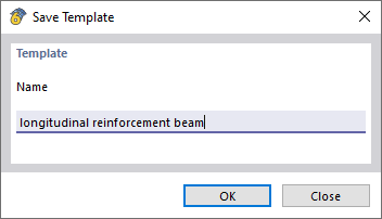
This template allows you to print the reinforcement of all or selected members with identically formatted reinforcement layout and view in the work window using the Multi Print function. First, enter a name for the template in the "Save Template" dialog box.
In the "Graphic Printout" dialog box – the general dialog box for printing graphics – select the Multi Print option in the "Main" tab. Then, you can select the relevant template in the "Graphic Templates" tab of the dialog box and define the members.


