


In the Shear Reinforcement tab, you can define the shear reinforcement that should be applied in the member shear design.

Spans
In this dialog box section, you can define the stirrup reinforcement areas. Only one entry is preset, which represents a kind of "basic reinforcement". You can adjust this default setting and divide the one large "span" into sections (see the image Defining Shear Reinforcement). Use the
![]() button at the end of the list to create new items.
button at the end of the list to create new items.
For the graphical representation of the stirrup reinforcement, it may be necessary to specify an 'offset' for the Border Distances of Stirrups.
Parameters
In this section, you can define the shear reinforcement properties. The parameters always refer to the span that is selected in the 'Spans' list on the left.
Base Data
Select the "stirrup type" from the list. Various stirrup shapes are available.
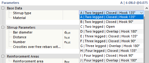
Assign material to the shear reinforcement. If you have already defined the right reinforcing steel in the model, it will be available for selection in the list. Otherwise, you can use the
![]() button in the text box to create a new material by accessing the material library in the
New Material
dialog box.
button in the text box to create a new material by accessing the material library in the
New Material
dialog box.
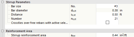
Stirrup Parameters
Specify the "Bar diameter" ds,st of the stirrups, the "Distance" ss,st between the stirrups or the "Number" ns,st of stirrups in the span. Usually, you only enter the stirrup diameter ds,st and the spacing ss,st. The amount of stirrups is obtained automatically. However, you can also specify the number of stirrups ns,st. The program determines the proper distance for the span. The reinforcement area of the provided stirrup reinforcement is shown in the category below.
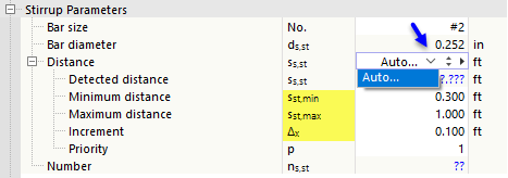
If you want the program to determine the diameter or the number for the design, select the Auto option.
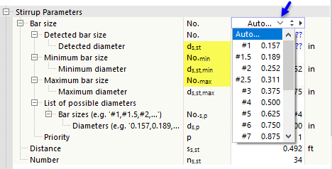
If the Bar diameter is to be determined, you can specify the smallest and largest possible diameters for the design. A user-defined list of possible diameters can be used to restrict the stirrup reinforcement to specific bar diameters.
If you want the program to determine the Distance, define the minimum and maximum allowable stirrup distance and the increment Δx for the design process.
Reinforcement Areas
Here, you can see the reinforcement area that results from the "Stirrup Parameters" entries. Alternatively, you can specify the reinforcement area asw directly in [cm²/m] or [in²/ft]. Based on this entry, the program determines the required distance ss,st and the resulting number ns,st of stirrups. The diameter ds,st remains the same.
Span Location
In this category, you specify where in the member the "span" with the stirrup reinforcement should be arranged. You can define this position with a "Reference" to the start, the end, or an x-location. Select the corresponding option in the list to define the reference point for the span location.

You can also use the "Definition format" to control whether the distances are to be specified in absolute length or relative percentage format.
Enter the "Start" x1 and the "End" x2 of the span. The "span length" ls represents the length of the stirrup section in the member.
Border Distances of Stirrups
The "layout rule" controls how the stirrups are positioned at the edges of the span. Several options are available.
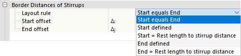
With the default setting "Start equals End", the program determines the remaining length from the number ns,st and the stirrup distance ss,st that is applied equally to the start and the end of the span. The text boxes for Δi and Δj are locked.
The other options allow you to manually define the border distances of the stirrups:
- "Start defined": Enter the start offset Δi that defines the position of the first stirrup in the span. The distance Δj at the end of the span is determined automatically; this value is not editable.
- "Start = Rest length to stirrup distance": This option is not possible for the first span, only for the following spans. Using this rule, the distances Δi and Δj are determined automatically; the values cannot be edited. If you clear the previous span, the option is automatically changed to "Start defined" and the previously determined value is entered as the start offset Δi.
- "End defined": Enter the end offset Δj that defines the position of the last stirrup in the span. The distance Δi at the end of the span is determined automatically; this value is not editable.
- "End = Rest length to stirrup distance": The program does not apply any start offset. The possible number of stirrups ns,st is determined based on the stirrup distance ss,st, and the remaining length at the end of the span is provided.
Information
Finally, here is the information about the stirrup reinforcement of the current span:
- Length of one stirrup Lst,1
- Length of all stirrups Lst as a sum
- Weight of one stirrup Wst,1
- Weight of all stirrups Wst as a sum
Graphic
In both graphic areas of the tab, you can see the reinforcement displayed graphically. On the right you can see the cross-section of the bar, below the longitudinal section. Your entries are implemented dynamically, thus providing you with a perfect control option.

Section
The graphic to the right shows the cross-section of the member with the stirrup and longitudinal reinforcement defined. The concrete cover is shown in the reinforcement layout. The cross-section graphic also shows the local axes z and y of the member.
The cross-section graphic refers to the reinforcement at "Location x" along the member specified in the text box below the graphic. With the default setting x = 0.000 m, the reinforcement is displayed at the member start. To display the reinforcement at a different member location, enter the corresponding distance. Location x is then indicated by an arrow in the longitudinal section.
The buttons below the graphic have the following functions:
|
|
Switches between cross-section graphic and model view |
|
|
Only shows the longitudinal reinforcement selected in the Positions list |
|
|
Shows or hides the member axes |
|
|
Shows or hides the dimensions of the cross-section |
|
|
Allows you to print the graphic in various ways |
Longitudinal Section
The graphic in the lower part of the dialog box shows the longitudinal section of the member, including the defined stirrup and longitudinal reinforcement, as well as the support symbols from the defined effective lengths and design supports.
To work in this graphic area, you can use all mouse functions described in the RFEM manual, the chapter titled Graphic Control. This allows you to zoom in on the reinforcement of the member or display it spatially.

The buttons next to the graphic have the following functions:
|
|
Allows you to set the view in various ways |
|
|
Enables the display in different member axis directions |
|
|
Enables the display as a wireframe model, solid model, or transparent model |
|
|
Shows or hides various auxiliary and model objects |
|
|
Represents the member symbolically in a horizontal or real position |
|
|
Allows you to print the graphic in various ways |
|
|
Opens the Reinforcement Layout window |
|
|
Shows the overall view of the member |


