The fire resistance design will be shown using an example from [3].
Example
The example includes a secondary beam of an intermediate ceiling. To prevent lateral-torsional buckling, it can be assumed that the upper chord has lateral supports. The required fire resistance class is R30. The structural system is shown in Image 01.
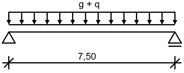
- Cross-Section
- HEM 280, S235, Wpl,y = 2,966 cm³
- Loading
- gk = 16.25 kN/m (permanent load)
- qk = 45.0 kN/m (imposed load category G)
Design with Normal Temperature Conditions
The governing action is the moment in mid-span.
Cross-Section Classification
The cross-section classification is based on [4], Table 5.2.
- Flange
- Web
The cross-section can be assigned to Class 1.
Design Value of Moment Resistance
According to [4] (6.13):
Design
Design according to [4] (6.12):
Determining Steel Temperature
Temperature Rise in Unprotected Steel Component
According to [1] (4.25):
|
ksh |
Correction factor for considering shadowing effect |
|
Am/V |
Section factor (represents the ratio of the exposed surface area to the volume) |
|
ca |
Specific heat capacity |
|
ρa |
Density of steel |
|
Δt |
Interval for the time step |
|
hnet,d |
Net heat flux |
Section Factor of Unprotected Steel Component
The section factor represents the ratio of the exposed surface area to the volume. In this case, the section factor is equal to the circumference of the steel cross-section minus the width of the upper flange, which is shaded by the ceiling, in relation to the cross-section area.
Section Factor for Box Enclosing Section
Correction Factor for Considering Shadowing Effect of I-Section
According to [1] (4.26a):
Standard Temperature-Time Curve
According to [2] (3.4):
Specific Heat Capacity
- For 20°C ≤ θa < 600°C according to [1] (3.2a):
- For 600°C ≤ θa < 735°C according to [1] (3.2b):
- For 735°C ≤ θa < 900 °C according to [1] (3.2c):
- Für 900°C ≤ θa ≤ 1.200°C according to [1] (3.2d):
The interval Δt for the time step method is selected as 5 s. The density of steel is ρa = 7,850 kg/m³ according to [1], Section 3.2.2 (1).
Net Heat Flux
- [2] (3.1)
- [2] (3.2)
|
αc |
Convective heat transfer coefficients for the standard temperature-time curve αc = 25 W/m²K acc. to [2], 3.2.1 (2) |
- [2] (3.3)
|
εm |
Emissivity of the structural component surface εm = 0.7 acc. to [1], 4.2.5.1(3) |
|
εf |
Emissivity of a flame εf = 1.0 acc. to [1], 4.2.5.1(3) |
|
σ |
Stephan-Boltzmann constant σ = 5.67 ⋅ 10-8 W/m2K4 acc. to [2], 3.1(6) |
|
Φ |
Configuration factor Φ = 1.0 acc. to [2], 3.1(7) |
For steel temperature θa and fire gas temperature θg, the start temperature is assumed to be room temperature of 20 °C. The increase of temperature for steel Δθa can be calculated step by step for each time interval Δt. The steel temperature for the next time step is obtained from the sum of the steel temperature of the previous step and the heating Δθa. Image 02 shows a partial view of the development of the steel temperature.
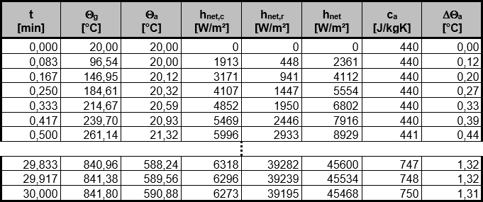
Thus, the governing steel temperature at the point of time t = 30 min is θa = 591°C.
Design for Fire Situation
Governing Action
The accidental design situation has to be used for the fire resistance design. The governing action is the moment in mid-span.
Cross-Section Classification
For the purposes of these simplified rules, the cross-sections may be classified as for normal temperature design with a reduced value for ε as given in [1], Equation (4.2).
- Flange:
- Web:
The cross-section can be assigned to Class 1.
Design Value of Moment Resistance
When determining the design value of the moment resistance, it is necessary to reduce the yield strength due to the increased temperature. For steel temperature θa = 591 °C, the reduction factor for the yield strength interpolated from [1], Table 3.1 results in:
For the unprotected beam with a reinforced concrete slab on one side and fire exposure on the other three sides, the adaptation factor κ1 according to [1], 4.2.3.3 (7) results in:
κ1 = 0.7
The temperature is distributed uniformly over the length. The adjustment factor κ2 according to [1], 4.2.3.3 (8) results in:
κ2 = 1.0
The design value of the moment resistance with uniform temperature distribution according to [1], 4.2.3.3 (4.8) results in:
The design value of the moment resistance with non-uniform temperature distribution according to [1], 4.2.3.3 (4.10) results in:
Design
Design according to [1] (4.1):
RF-STEEL EC3
The example is calculated in RF-/STEEL EC3. You can download the corresponding model files for RFEM and RSTAB at the end of this article.
General Data
Member 1 will be designed. For the design under normal temperature, select the load combinations for the permanent/transient design situation according to Equation 6.10 in the "Ultimate Limit State" tab and the load combinations for the accidental design situation according to Equation 6.11c for the fire resistance design in the "Fire Resistance" tab (Image 03).

Effective Lengths – Members
Lateral-torsional and torsional-flexural buckling is prevented so that the corresponding check box is cleared in Window "1.5 Effective Lengths - Members" (Image 04).

Details
The required time of fire resistance, the temperature curve, and the coefficients to determine the net heat flux are defined in the "Fire Resistance" tab of the "Details" dialog box (Image 05).

Fire Resistance – Members
Define the fire resistance parameters such as fire exposure and fire protection measures in the "1.10 Fire Resistance – Members" window (Image 06). The unprotected beam is exposed to fire on three sides.

Results
The results are displayed after the calculation (Image 07). The intermediate values relevant for the fire resistance design, such as steel temperature, are also displayed in the "Details" table.

7
Results


.png?mw=350&hash=dc38fc2ddc3754a07164885d9707318b00be194d)


-querkraft-hertha-hurnaus.jpg?mw=350&hash=3306957537863c7a7dc17160e2ced5806b35a7fb)


.png?mw=600&hash=49b6a289915d28aa461360f7308b092631b1446e)


