It is advisable to calculate the stiffness of the connection first rather than performing the design of the strength configuration: The classification and the corresponding rigidity of the joint have an effect on the internal forces of the model, which in turn affects the stresses of the steel joint.
Stiffness Analysis
The calculation of the connection stiffness Sj,ini can be launched independently of the Strength design. Start that part of the calculation by clicking the
![]() button on the table toolbar.
button on the table toolbar.

A small window is opened where the calculation progress is shown.

As soon as the calculation has finished, the results are presented in the 'Stiffness Analysis' table.

The axial stiffness and rotational stiffness are listed for the 'Frame girder' component as the calculation has been set for that component only (see the Selecting Internal Forces for Stiffness Analysis image). Those values represent the rigidities of the joint due to its constructive design (end plate, bolts, welds).
Switch to the Classification table.

This table shows the 'Classification' of the joint. It is based on the results of the stiffnesses and the limit values given in the 'Classification Boundaries' columns. As both nodes are classified as 'Semi-rigid', the model ought to be adjusted: The frame girder beam was defined without any member hinges. This model represents a rigid connection to the column instead of a semi-rigid joint.
Applying Stiffness Analysis Results on Model
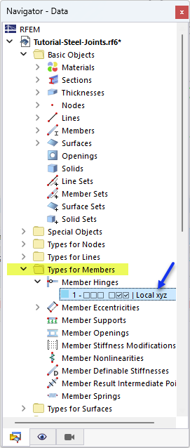
To apply the spring constants of the semi-rigid connection for the frame girder, a new type of member hinge is needed. Open the Types for Members category in the 'Navigator - Data'. Then open the Member Hinges types and double-click the hinge type no. 1.
In the 'Edit Member Hinge' dialog box, click the
![]() button (1) to define a new type of hinge. Then enter the values of the spring constants as specified in the 'Classification' table (2):
button (1) to define a new type of hinge. Then enter the values of the spring constants as specified in the 'Classification' table (2):
- Cφ,y = 3960.901 [kipft/rad] (the value will be rounded)
- Cφ,z = 111.568 [kipft/rad]

For Cφ,y, the SMy- value is applicable as there are negative bending moments My at both ends of the frame girder. Cφ,z does not really matter for the model because there are no moments Mz. The translational component ux of the hinge can be neglected: The frame girder has compressive forces and the axial stiffness for compression is infinite (see the Table 'Stiffness Analysis' image).
Click OK to close the dialog box. To assign the new type of hinge, right-click that item in the 'Navigator - Data'. Then select the Assign to Members option in the shortcut menu.

The members are divided graphically in thirds. Select the parts of the frame girder that are connected to the columns:
- Member 4 - Start (click the part next to the column)
- Member 11 - End (click the part next to the column)

Click OK in the 'Members Assignment' window to allocate the hinges.

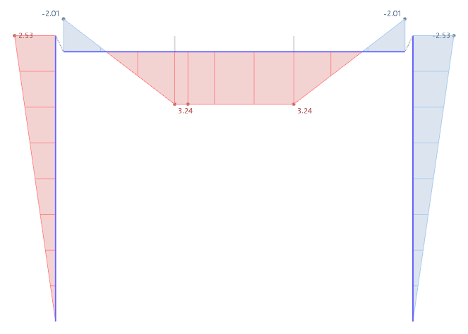
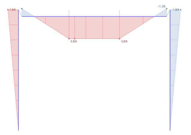
Impact on Moments
Taking account of the initial stiffness by means of member hinges results in a modified distribution of moments for the frame girder and columns. The moments My at the connection are significantly reduced, while they are increased in the inner span due to the redistribution. The following images, which are only for your information, show the differences.


-querkraft-hertha-hurnaus.jpg?mw=350&hash=3306957537863c7a7dc17160e2ced5806b35a7fb)


