To complete the example, the two inner beams are each to be connected to the upper flange of the frame girder by two bolts.
Double-click one of the steel joints in the work window so that the 'Edit Steel Joint' dialog box is opened again. Then click the
![]() button at the end of the 'List' to create a new type of steel joint.
button at the end of the 'List' to create a new type of steel joint.
Click the
![]() button in the 'Assigned to Nodes No.' area. Then select the two inner nodes nos. 20 and 22 by clicking them one by one in the work window.
button in the 'Assigned to Nodes No.' area. Then select the two inner nodes nos. 20 and 22 by clicking them one by one in the work window.
Click OK to return to the dialog box where the node numbers are set now. In the 'Assignment of Members' area, the program created three "Members" again that are based on the topology of the selected nodes.
The default configuration is set for the Strength design. As this type of connection is not to be classified, no stiffness analysis configuration (--) is suitable here.
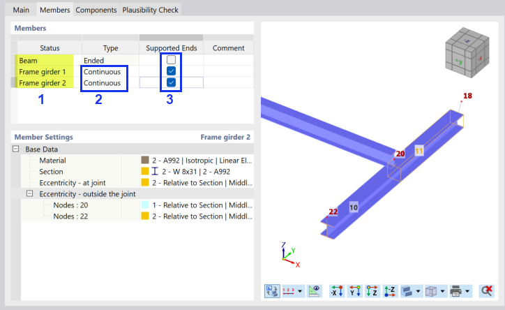
Go to the Members tab. By selecting a member type in the 'Status' column, you can check its location within the model view to the right. You can rename the member types for a better overview: Replace 'Member 1' by Beam, 'Member 2' by Frame girder 1, and 'Member 3' by Frame girder 2 (1).
As the frame girder does not end in either of the nodes, change the 'Type' to Continuous for both frame girder members (2). You can select that type from the list as soon as you have clicked the 'Ended' text box.
Similarly, assign the Supported Ends option to both frame girders by selecting the two check boxes and by clearing the check box for the grid girder (3).
Then switch to the Components tab.
Member Cut
In the first step, the grid girder is extended to the outer edge of the frame girder by means of the "Member Cut" component. Click the
![]() button in the 'Components' area.
button in the 'Components' area.
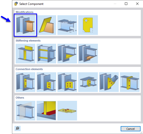
In the 'Select Component' window, select the Member Cut component type by clicking it.
You return to the 'Components' tab where the member cut is set as new component type.
In the 'Component Settings' area, select the Farther option in the list to define the 'Cutting plane' (1). You can see in the preview how the end of the beam is adjusted.
Click the
![]() button in the 'Components' area to insert the next component (2).
button in the 'Components' area to insert the next component (2).
Fasteners
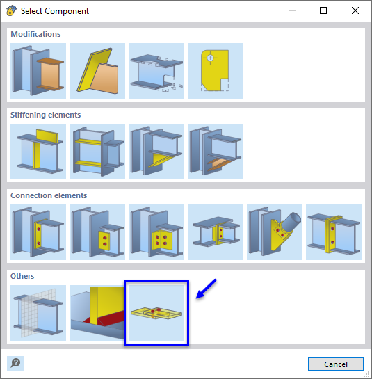
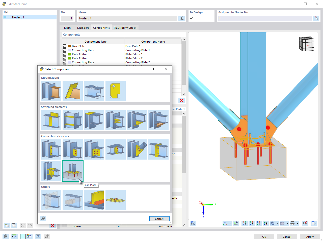
The 'Select Component' window is opened.
Select the Fasteners component type by clicking the button. You return to the 'Components' tab again where the fasteners are set as a new component.
In the 'Component Settings' area, the components must be specified that are to be connected. Click the first '--' box in the line of Component 1. Then open the list where you select the Member plate option.
Then select the box to the right and open its list. Select the Beam | Flange 2 option (1). The part of the girder is highlighted in the preview.
Click the '--' box of Component 2 in the next line and select Member Plate in the list again (2). In the '??' list to the right, select Frame girder 1,2 | Flange 1 (3).
As the flange of the beam was set as first component that is to be connected, it represents the 'Origin' of the fastener.
The number and distances of the bolts are to be adjusted. Set the following parameters in the 'Bolts' area.
| Number | Spacing longitudinally | 1 (1) |
| Distance 1 | 2.0 in (2) |
| Number | Spacing transversely | 2 (3) |
| Distance 1 | 1.0 in (4) |
| Shear plane in thread | Disabled (5) |
The component settings should then look like in the following image.
Switch to the Plausibility Check tab. The connection is correctly defined as no errors are detected by the program.
Click OK to close the dialog box. In the work window, the connection is displayed at the two inner nodes.











_1.jpg?mw=350&hash=ab2086621f4e50c8c8fb8f3c211a22bc246e0552)
