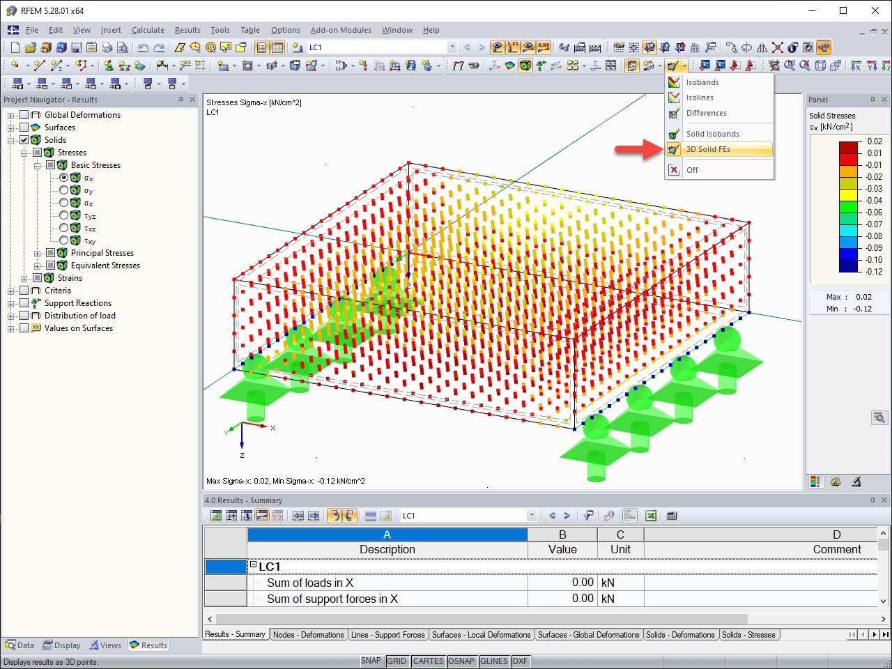
You can also examine the design results graphically on the model, which gives you a good insight into the conditions of each connection. Make sure that the 'Detailed Joint Model' view is still active (if necessary, you can set it via the
![]() button on the toolbar, see the
Displaying Detailed Joint Model
image). The 'Wireframe Model' view – symbolized by the
button on the toolbar, see the
Displaying Detailed Joint Model
image). The 'Wireframe Model' view – symbolized by the
![]() button – should be still set.
button – should be still set.
Navigator and Control Panel
In the Navigator - Results (
![]() tab), you can control the graphical results displayed for the component types by selecting or clearing the check boxes. The following components are relevant for the steel joint:
tab), you can control the graphical results displayed for the component types by selecting or clearing the check boxes. The following components are relevant for the steel joint:
- Members and plates
- Fasteners
- Welds
The control panel has only four colors by default. They mean:
|
|
No or only low utilization |
|
|
Medium utilization |
|
|
High utilization |
|
|
Exceeded utilization |
When you use the mouse functions to zoom in the area around the corner node no. 17 and rotate the model a bit, you will see that the members and plates are blue, the fasteners of the end plate are orange, and the welds are blue (see the Graphical Results of Stress-Strain Analysis image). You can immediately see that the bolts are decisive for this connection.
Modifying Colors
Double-click one of the colors in the control panel. In the 'Edit Result Colors' dialog box, select the Default | Ratio (11 colors) scale that is common for design results.
Click OK to apply that color scale.
Selecting Components
Disable the Members and plates option in the navigator so that only the results of the bolts and welds are shown.
When you rotate the model a bit further, you will see that the red bolts of the frame girder represent a high design ratio while the light blue bolts of the beam stand for a low utilization. The welds also have relatively low design ratios.
Finally select the Members and plates check box in the navigator again to restore the default settings.


.png?mw=350&hash=c6c25b135ffd26af9cd48d77813d2ba5853f936c)


![Basic Shapes of Membrane Structures [1]](/en/webimage/009595/2419502/01-en-png-png.png?mw=512&hash=6ca63b32e8ca5da057de21c4f204d41103e6fe20)


.png?mw=512&hash=ea9bf0ab53a4fb0da5c4ed81d32d53360ab2820c)


_1.jpg?mw=350&hash=ab2086621f4e50c8c8fb8f3c211a22bc246e0552)


