A cap plate is a steel plate arranged at the upper end of a column perpendicular or inclined to the member axis, thus completing the cross-section.

To Stiffen
The first category of the component settings manages the information about the members and the section type.
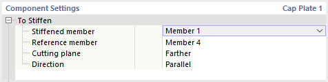
Specify which of the members connected to the node is relevant for the cap plate as a Stiffened member. Usually, it is a column. The Reference member is optional. However, this is useful if a beam is connected at an angle: The inclination angle is then automatically applied to shear the cap plate.
If you define a reference member (for example, a horizontal beam), you can select the Section plane: It can be located either at the more distant end (at the top of the column head) or at the closer end of the joint (at the bottom flange of the girder). On the other hand, the Direction determines whether the cap plate is arranged parallel to the girder flange or perpendicular to the column. These parameters are described in detail in the chapter Member Cut.
Plate
In this category, you can define the plate properties. Select the relevant material from the defined materials or define a new material using the
![]() button. Then, enter the thickness of the cap plate.
button. Then, enter the thickness of the cap plate.
You can define the cap plate geometry by using Offsets or Dimensions and position. Select the corresponding option in the list.
Offsets
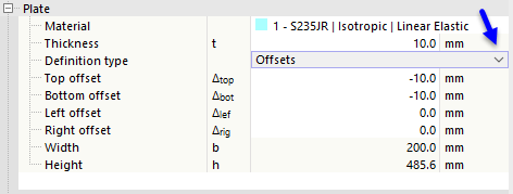
The basic plate size results from the cross-section dimensions of the connected member. By defining the Offset in the four directions, you can define how far the cap plate protrudes beyond the bounding box of the cross-section. The resulting width and height are indicated in the last rows; these values cannot be modified.
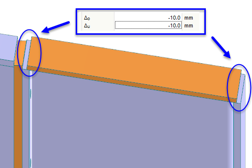
You can define recesses of the cap plate, which are required for applying a weld, by using negative offsets Δo and Δu.
Dimensions and Position
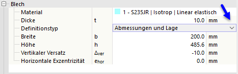
You can specify the plate size directly. The position is related to the stiffened member, with the vertical offset being measured from the top of the column (the cross-section side of the negative z-axis) and the horizontal eccentricity from the centroid of the member cross-section.
Position
This category allows you to place the cap plate at a distance from the member end and to rotate it. However, if you have defined a reference member, you do not need to adjust the cap plate manually: The parameters result automatically from the position of the reference member and the specifications in the To Stiffen category.
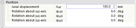
The Axial displacement refers to the definition node of the member. Depending on the member orientation, it is necessary to enter the distance specifications as a positive or negative value. When moving the cap plate, the member end is also moved, without the need for a member cut.
You can apply a Rotation of the cap plate using the angles φ. The axes x, y, and z refer to the coordinate system of the cap plate, which you can display in the graphic to the right by clicking the
![]() button.
button.
Welds
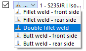
The last category controls the welds used to connect the cap plate to the edges of the column cross-section. If you deactivate one of the check boxes, no weld is arranged on the corresponding cross-section part.
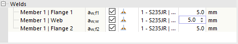
You can open a list of weld types by clicking in the column to the right of the check box. Various types of fillet and butt welds are available for selection. For fillet welds, you have to specify the thickness of the weld.