


The Rib component is used in steel connections to increase the stiffness and load-bearing capacity of the connection. It is typically used as a reinforcement element on a steel plate or cross-section. In contrast to a stiffener, the rib runs along the member axis instead of across it.

To Stiffen
The first category of the component settings manages the general information about the rib arrangement.
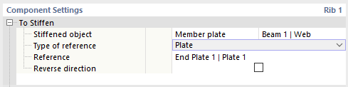
First, specify which object type is to be stiffened. You can select from two options in the Stiffened object list:
- Member: The rib is arranged in relation to the cross-section of the entire member.
- Member plate: You can specify a cross-section part of the member (“plate”); for example, the web.
Then, select the member or cross-section part from the list in the last column.
Specify the Type of reference in the list to place the rib in relation to the object. This can be a plate, a member, or an auxiliary plane. Then, select the Reference object from the list. You can place the rib based on the coordinate system of the reference component.
If you select the Reverse direction check box, the rib will be placed on the other side of the stiffened object.
Position
In this category, you define the location where the rib is to be arranged. If the object is stiffened with several ribs, you can also enter the corresponding specifications here.

Specify the Side where the rib reinforces the object. When stiffening a member plate, you can select from the following options in the list:
- Front (in the direction of the positive y-axis of the rib)
- Rear (opposite to the positive y-axis of the rib)
- Both
When stiffening a member, ribs are added to all sides of the surface area of the cross-section that can be selected from the list: Top, Bottom, Right, and Left. The designations refer to the rib coordinate system as follows:
- Top (in the direction of the positive z-axis of the rib)
- Bottom (opposite the positive z-axis of the rib)
- Right (in the direction of the positive y-axis of the rib)
- Left (opposite the positive y-axis of the rib)
Specify the Number of ribs. The Distance of the rib is preset to zero in order to place it in the center of gravity of the object. You can move the rib by adjusting this value. A positive distance moves it in the direction of your local z-axis. If you define multiple ribs, the other values in the group describe the distances between the individual ribs.
Plate
In this category, you can define the properties of the ribbed plate.
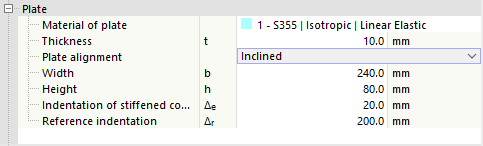
Select the corresponding "Material" from the defined materials, or create a new material using the
![]() button. Then, enter the Thickness of the plate.
button. Then, enter the Thickness of the plate.
The Plate alignment controls how the plate is constructed. Two options are available in the list:
- Parallel: A plate parallel to the object with a constant width
- Inclined: A chamfered plate
Then enter the Width (length) and Height of the rib and, if applicable, the Indentation of stiffened component and the Reference indentation of the rib to define the chamfer. In the graphics area, you can switch to the symbol display using the
![]() button, where the parameters are illustrated.
button, where the parameters are illustrated.
Welds
The last category controls the welds used to connect the rib at the edges of the stiffened object and the reference object. If you deactivate one of the check boxes, no weld is arranged on the corresponding cross-section part.
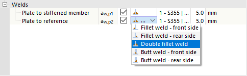
You can open a list of weld types by clicking in the column to the right of the check box. Various types of fillet and butt welds are available for selection. For fillet welds, you have to specify the thickness of the weld.
