


There are two ways to adjust members at a joint. First, you can enter a member cut to completely cut off the member and adapt it to the connected structural component. Second, you can use the Member Editor to specifically adjust the cross-section's corners, and thus model the details in the joint area. In the member editor, it is possible, for example, to round the member end or to provide it with a notch.

Modification Settings
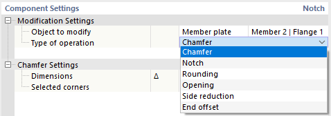
First, define the object type you want to adjust. In the "Object to Modify" list, two options are available for selection:
- Member: The modification affects the cross-section of the entire member.
- Member plate: You can adjust a cross-section part of the member ("plate"), for example, a flange or a web.
Then, select the last column of the member or the cross-section part in the list.
In the second line, enter the "Type of operation" by which you want to adjust the member or the plate. Depending on the object, different options are available in the list.
Settings
The type of operation affects the parameters that you have defined in the second category.
Chamfer
The chamfer allows you to provide a member or a cross-section part with a chamfer.

Specify the dimensions Δ of the recess. The first parameter represents the height, the second parameter the length. In the graphics area, you can switch to the symbol display using the
![]() button.
button.
Then, specify the sides of the members or corners of the cross-section part that you want to chamfer. The numbers of sides or corners are shown in the graphic. If you want to chamfer all sides or corners evenly, select the “All” option from the list.
Notch
You can specify a notch for an entire member or for part of the cross-section of a member (for example, the flange or web).

Specify the dimensions Δ of the recess. The first parameter represents the height, the second parameter represents the length of the notch. In the graphics area, you can switch to the symbol display using the
![]() button.
button.
If the notch is rounded, specify its radius. Finally, define the relevant sides of the members or corners of the cross-section part. The numbers of sides or corners are shown in the graphic.
Rounding
The Rounding option allows for the rounding of the corners of a cross-section part.

Specify the radius of the rounding. Then, define the relevant corners of the cross-section part. The numbers of corners are shown in the graphic.
Opening
The Opening creates a hole in the cross-section part. This way, you can model a round or angled opening in the web or flange of a section.

Select the shape of the opening in the list. The following options are available:
- Circle
- Rectangle
- Polygon
- Hexagon
Then, define the parameters of the opening. The specifications are aligned with the shape of the opening. In the graphics area, you can switch to the symbol display with parameters using the
![]() button.
button.
Side Reduction
The side reduction allows for a small recess at the edge of a cross-section part.

Define the relevant sides of the cross-section part. The numbers are shown in the graphic. If you want to make a cut on both sides of the flange or web, select the “All” option from the list.
Select the "shape" of the side reduction from the list. The following options are available:
- Trapezoidal
- Arch
Then, define the parameters of the reduction. The specifications are adjusted to the shape. In the graphics area, you can switch to the symbol display with parameters using the
![]() button.
button.
End Offset
With an end offset, you can cut off a cross-section part at the member end.

Define the length Δ of the offset.