


The Steel Joint add-on is fully integrated in RFEM. Therefore, you can use all options known from the main program to document the graphical results of the design ratios and buckling analysis. The general procedure of preparing graphics for printout is described in the chapter Graphics of the RFEM manual.
Graphics of Work Window
In the chapter Graphic for Steel Joint Design, all result types that are graphically available for the components are presented. You can print the current view directly using the print function, or transfer it to the printout report.
In the '"Graphic Printout" dialog box, specify the print settings for the image as usual.

If you activate the Multi Print option in the "Window" category, you can define the specifications for printing several windows or the mass print of graphics in the "Add-ons" tab (see the chapter Using Multi Print of the RFEM manual). The graphics are then sorted in the printout report with the Steel Joint Design results.

Steel Joint
The Steel Joints dialog box provides further options to graphically document the steel joint.

The "Components" tab with the 3D graphic of the connection objects is particularly suitable for printing the connection geometry, as it is required for the production, for example.
Design Check Details
Functions are also available in the Design Check Details dialog box that allow you to print the design equations in the form of graphics.

Results in Steel Joint
The Results in Steel Joint window also provides functions for printing the joint graphics.

Templates for Steel Joints
In the tabs of the Steel Joint dialog box, you can save the current settings as a template and use them in other models for graphic printout. To do this, use the Print as template option in the list button
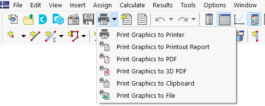
![]() of the toolbar (see the image Printing Steel Joint Graphic).
of the toolbar (see the image Printing Steel Joint Graphic).
This template allows for the printing of the joints of all or selected members with identical joint modeling and view in the working window using the Multi-Print feature. First, enter a name for the template in the “Save Template” dialog box.

In the “Graphic Printout” dialog box – the general dialog box for printing graphics – activate the Multi-Print option in the “General” tab. You can then select the appropriate template in the “Graphic Templates” tab and specify the members.

- banner.tip@The FAQ Graphic Templates for Printing Reinforcement Layout describes how to use templates for concrete design. The same applies to the documentation of steel joints.
Managing Templates
You can rename or delete a template later. To do this, use the RFEM menu “Options” → “Graphic Templates.” All user-defined templates are listed in the “Graphic Template” dialog box.

Click an entry in the “Name” column to assign a different name. If you want to delete a template, click its number in the first column. Clicking the
![]() button removes the template from the list.
button removes the template from the list.