Many components include inserting plates; for example, an End Plate, Fin Plate, Connecting Plate, and so on. You can also insert a plate as a separate component, for example, acting as a cap plate of a column, a stiffener of an open section, or a gusset plate on which you connect a member using the Connecting Plate component. In the image below, you can see a cap plate and a gusset plate.
Element
In the first category of the "Component Settings", the dimensions of the plate and its material are to be defined. You can select from the existing materials or define a new one.
Position
The next category controls the positioning of the plate in the joint.
Origin
Select the "Origin" component that the displacements and rotations of the plate are to be related to.
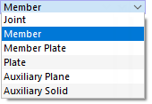
The default setting is Joint, meaning the origin of the whole joint. You can also select a Member, Member Plate, another Plate, an Auxiliary Plane or Auxiliary Solid as the reference component. Based on the coordinate system of that component, you can move and rotate the plate to adjust its arrangement.
Origin alignment
This option is available when a member has been set as the origin. You can select the reference point of the cross-section where the plate is to be attached.
There are two lists with three options each.
| Center | The center of the plate refers to the centroid of the cross-section. |
| Top | The center of the plate refers to the upper edge (bounding box) of the cross-section located in the negative z-direction. |
| Bottom | The center of the plate refers to the lower edge (bounding box) of the cross-section located in the positive z-direction. |
| Center | The center of the plate refers to the centroid of the cross-section. |
| Left | The center of the plate refers to the left edge (bounding box) of the cross-section located in the negative y-direction. |
| Right | The center of the plate refers to the right edge (bounding box) of the cross-section located in the positive y-direction. |
Object alignment
Here you can select the reference point ("grab point") of the plate used to connect it.
There are three lists with three options each.
| Center | The plate is set at the center line which refers to its x-axis. The next columns control the specific point. |
| Top | The plate is aligned to its upper edge which is defined by the reference point located in the positive x-direction of the plate. |
| Bottom | The plate is aligned to its lower edge which is defined by the reference point located in the negative x-direction of the plate. |
| Center | The plate is set at the center line which refers to its y-axis. The other columns control the specific point. |
| Left | The plate is aligned to its left edge which is defined by the reference point located in the negative y-direction of the plate. |
| Right | The plate is aligned to its right edge which is defined by the reference point located in the positive y-direction of the plate. |
| Center | The plate is set at the center line which refers to its z-axis. |
| Front | The plate is aligned to its front side which is defined by the reference point located in the positive z-direction of the plate. |
| Rear | The plate is aligned to its rear side which is defined by the reference point located in the negative z-direction of the plate. |


