The pushover analysis is based on a load combination with the Pushover Analysis type assigned.
Main
In the Main tab, you can assign the analysis types and define additional parameters. To do this, select the load combination in the "list" on the left.
Categories
This section covers basic settings for a pushover analysis of the load combination.
Analysis Type
Once you have activated the "Pushover Analysis" add-on in the model's Base Data, the "Pushover Analysis" is available in the list. Assign this analysis type to a load combination for which you want to perform the pushover analysis. We recommend creating a user-defined load combination for this.
Static Analysis Settings
In the list of Static Analysis Settings, specify the analysis type according to which the calculation of the pushover load combination will be performed.
Pushover Analysis Settings
In the list of "Pushover Analysis Settings" (PA), select the specifications used for the analysis of the load combination. These include, for example, the specifications for the load increment, stopping conditions, and the accuracy for the calculation of the target displacement. These parameters are described in the chapter Pushover Analysis Settings.
You can use the
![]() button to add new time pushover analysis settings, and the
button to add new time pushover analysis settings, and the
![]() button to edit the selected settings.
button to edit the selected settings.
Constant Vertical (Gravity) Loads from Load Case / Load Combination
Define the load case or load combination whose loads are to be considered as constant (unvariable) in the pushover analysis. All load cases and combinations that are analyzed according to the same static analysis setting as the pushover load combination are available for selection in the list. In the pushover analysis, this load component is not increased.
Horizontal (Increasing Load) Source
In this section, you can enter specifications for loads that laterally act on the structure. In the pushover analysis, these loads are increased until the break criterion is reached or the structural system fails.
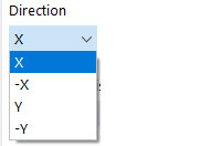
Direction
In the list, select the global axis in whose direction the loads act.
Modal Analysis from Load Case
In the list of the defined modal analysis load cases, specify which eigenvalue analysis should form the basis of the pushover analysis. This modal analysis load case is a prerequisite for the calculation of the masses and the load distribution according to the modal shape.
Normalized Displacements
The following options are available for selection in the list:
- Uniform (1 in direction of earthquake, 0 otherwise): The load is applied uniformly over the building height at the mass points of the structure. The lateral load is only determined by the mass distribution and is not scaled further. The horizontal forces are proportional to the masses—regardless of the altitude—and thus correspond to a uniform acceleration response.
- Modal (automatic modal shape): The load is scaled by the dominant mode shape and applied to the mass points of the structure in the specified direction. The horizontal forces are thus proportional to the masses and heights/mode shapes.
- Modal (user-selected modal shape): The load is scaled by the user-defined mode shape and applied to the mass points of the structure in the specified direction.
Mode Shape Φ
This text box is only available for a user-defined modal shape. It allows you to scale the mode shape by adjusting the vector of the normalized displacement Φ.
Response Spectrum
In the Response Spectrum tab, you can assign the response spectrum to be considered in the pushover analysis.
In the list, select one of the existing response spectra that should be applied for the determination of the target displacement. You can use the
![]() button to create a new reinforcement type, and the
button to create a new reinforcement type, and the
![]() button to edit the selected settings.
button to edit the selected settings.
Further information about this tab can be found in the chapter Response Spectrum.


