When the calculation has finished, you can examine the results in the tables, in the graphics, and in a specific window.
Design Results

Subchapters
Parent Chapter


Duration: 00:01:19 min

Duration: 01:10:25 min

Duration: 00:59:06 min

Duration: 00:00:32 min

Duration: 00:51:02 min

Duration: 00:01:06 min

Duration: 00:00:30 min

Duration: 00:01:11 min

Duration: 00:00:52 min


Consideration of p-δ Second-Order Effects in RFEM 6 and RSTAB 9

For reinforced concrete components and structures whose structural behavior is significantly influenced by the second-order effects, Eurocode 2 provides the general method based on a nonlinear determination of internal forces according to the second-order analysis (5.8.6), as well as an approximation method based on the nominal curvature (5.8.8).
The aim of this technical article is to perform a design according to the general design method of Eurocode 2, using the example of a slender reinforced concrete column.
The aim of this technical article is to perform a design according to the general design method of Eurocode 2, using the example of a slender reinforced concrete column.

This technical article addresses the direct deformation analysis of reinforced concrete beams considering the long-term effects of creep and shrinkage. The direct calculation according to Eurocode 2 (EN 1992-1-1, Section 7.4.3) is explained using a single-span beam. Particular emphasis is placed on tension stiffening, behavior in the cracked state based on the distribution factor (damage parameter), and consideration of shrinkage and creep behavior.
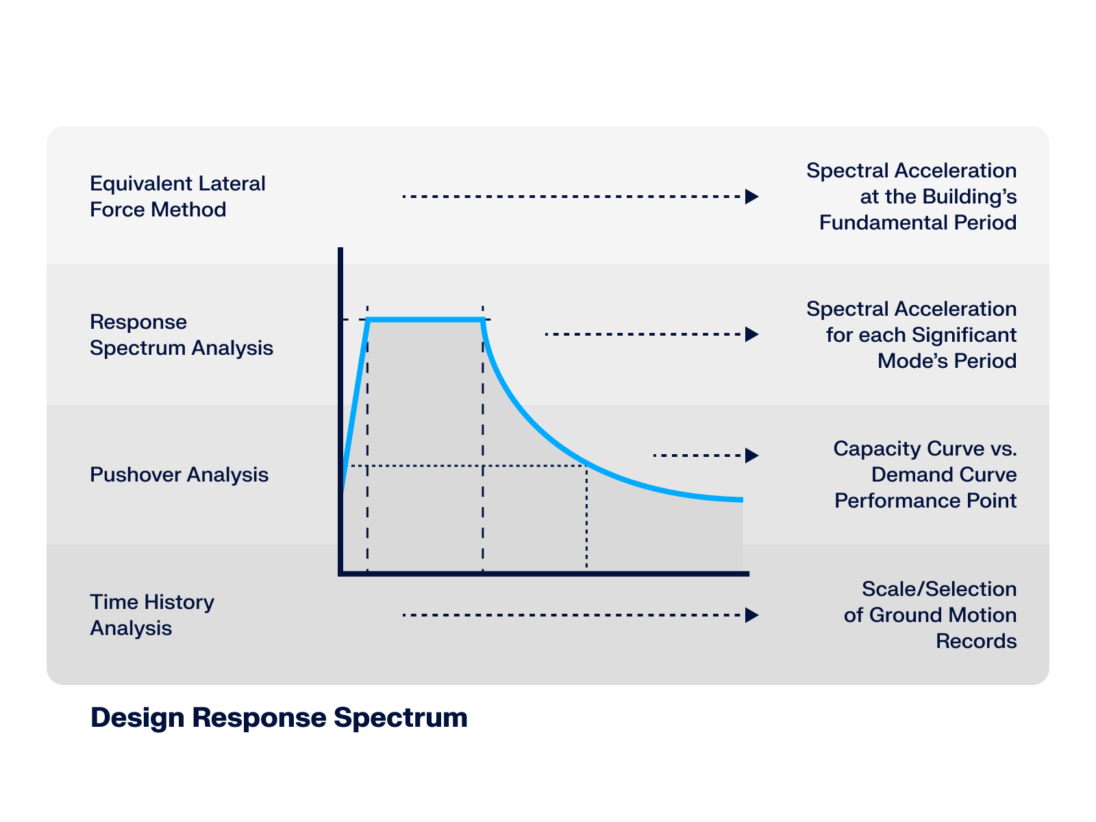
This article* explores the role of the Design Response Spectrum across different seismic analysis methods, demonstrating its significance from simplified static approaches up to advanced dynamic simulations.


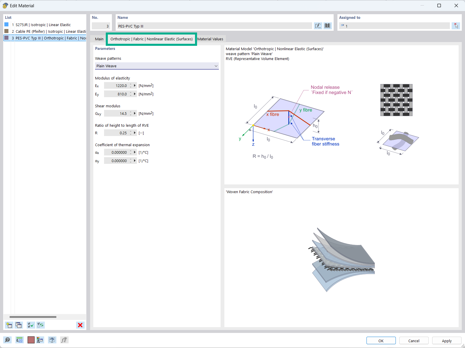
The "Orthotropic | Fabric | Nonlinear Elastic (Surfaces)" material model allows you to define prestressed fabric membranes using the representative microstructure-solid element model – RVE.
By considering the fabric geometry in the microstructure model, the corresponding transversal strain effect can now be considered for all force conditions in the membrane.
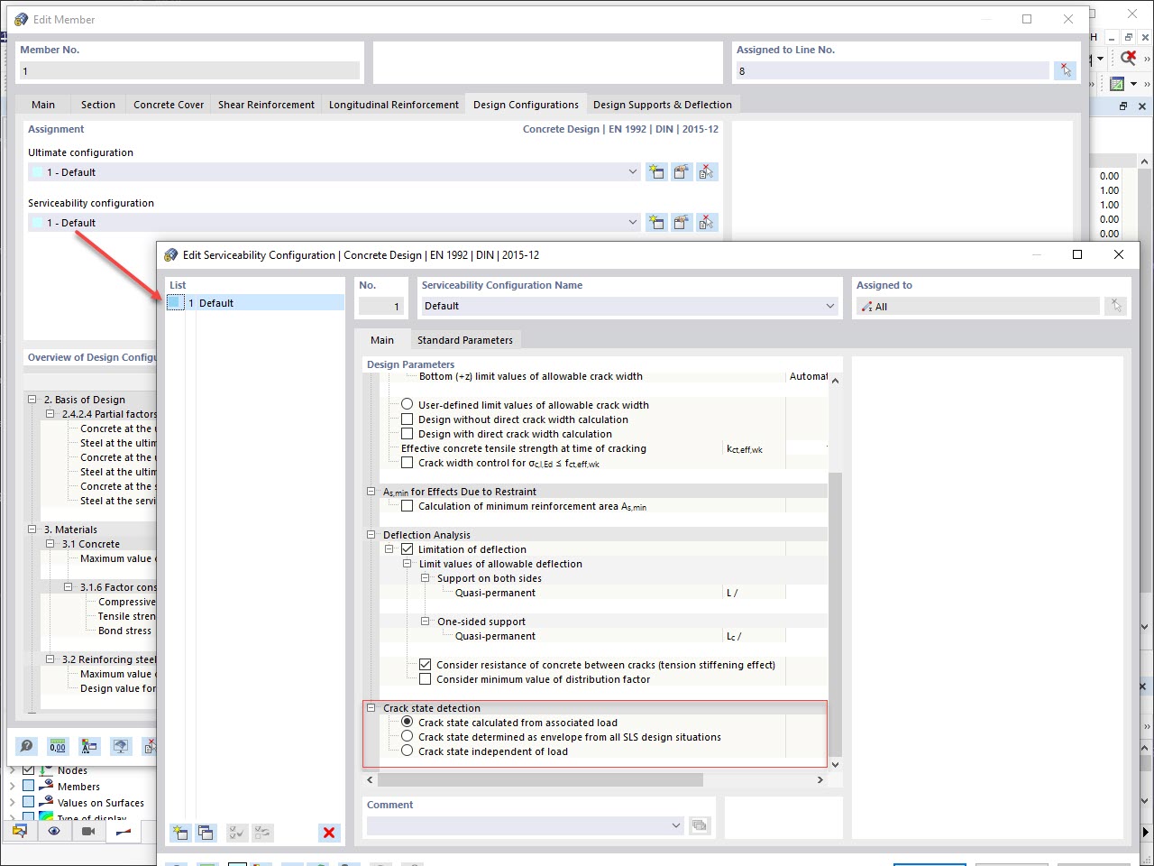
Various design parameters of the cross-sections can be adjusted in the serviceability limit state configuration. The applied cross-section condition for the deformation and crack width analysis can be controlled there.
For this, the following settings can be activated:
- Crack state calculated from associated load
- Crack state determined as an envelope from all SLS design situations
- Cracked state of cross-section - independent of load
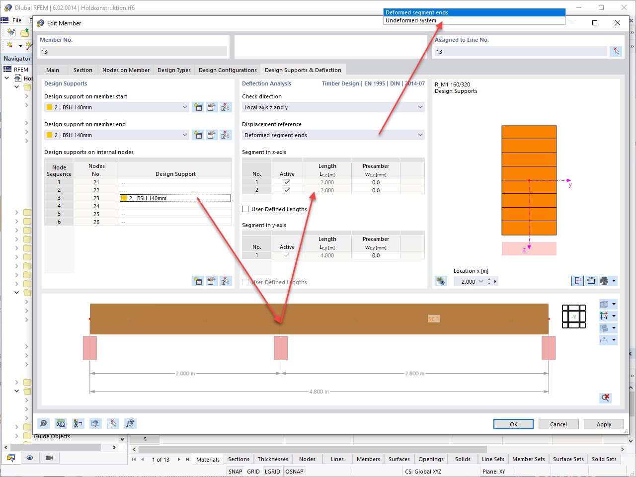
In the "Deflection and Design Support" tab under "Edit Member", the members can be clearly segmented using optimized input windows. Depending on the supports, the deformation limits for cantilever beams or single-span beams are used automatically.
By defining the design support in the corresponding direction at the member start, member end, and intermediate nodes, the program automatically recognizes the segments and segment lengths to which the allowable deformation is related. It also automatically detects whether it is a beam or a cantilever due to the defined design supports. The manual assignment, as in the previous versions (RFEM 5), is no longer necessary.
The "User-Defined Lengths" option allows you to modify the reference lengths in the table. The corresponding segment length is always used by default. If the reference length deviates from the segment length (for example, in the case of curved members), it can be adjusted.
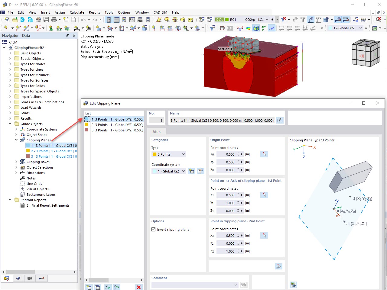
This feature also contributes to the clearly-arranged display of your results. Clipping planes are intersecting planes that you can place freely throughout the model. The zone in front of or behind the plane is consequently hidden in the display. This way, you can clearly and simply show the results in an intersection or a solid, for example.
How can I define a plastic hinge in RFEM 6?
How can I connect surfaces to other surfaces or members in a hinged/semi-rigid way?
What are Line Hinges and Line Releases?
What are Line Hinges and Line Releases?
Why is the effective depth different with the effective depth used in shear checks?
Can I optimize parametric cross-sections?
How can I check the determination of the required reinforcement?
Is it possible to consider shear panels and rotational restraints in the global calculation?


