It is necessary to adjust the model slightly so that the connections can be defined in a simple way.
If any results are shown, switch them off by clicking the
![]() button on the toolbar. Then make sure that the Wireframe Model view is active. You can set it by selecting the
button on the toolbar. Then make sure that the Wireframe Model view is active. You can set it by selecting the
![]() option from the
option from the
![]() list button.
list button.
Dividing Frame Girder
The frame girder was modeled as a single continuous beam. To create steel joints where the smaller grid girders frame into the girder, the frame girder must be split up.
Click the
![]() button on the toolbar so that the "Connect Lines/Members" function is activated. Then, draw a window over the entire frame girder.
button on the toolbar so that the "Connect Lines/Members" function is activated. Then, draw a window over the entire frame girder.
When the program asks you whether all results are to be deleted because of the modification, click Yes. Then, the continuous line of Member 4 is split up.
Right-click in an empty area of the workspace or press Esc to quit the function.
Adjusting Member Eccentricities
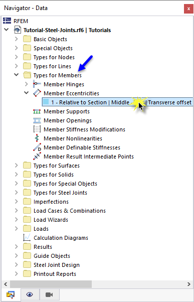
The member eccentricities resulting from the division need to be adjusted. Select the Navigator – Data and then open the Types for Members category. In the Member Eccentricities category, double-click the eccentricity type no. 1 - Relative to Section.
In the "Edit Member Eccentricity" dialog box, click the
![]() button to copy the selected member eccentricity.
button to copy the selected member eccentricity.
Clear the Axial offset from adjoining member option.
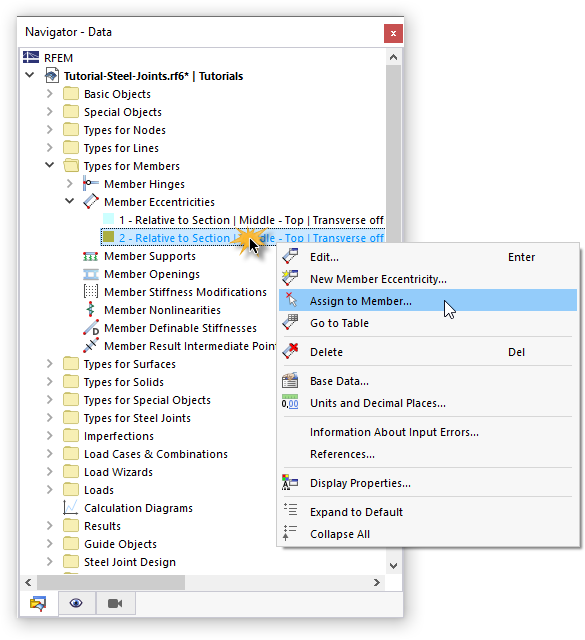
Click OK to close the dialog box. To assign the new type of eccentricity, right-click that item in the "Navigator - Data". Then, select the Assign to Member option in the shortcut menu.
The members are divided graphically in thirds. Select those parts of the frame girder where the inner grid girders are connected:
- Member 4 - End (click the right part)
- Member 10 (click the center part to allocate it to both ends)
- Member 11 - Start (click the left part)
Click OK in the "Members Assignment" window to allocate the eccentricities.
You can check the modifications in the "Transparent Model" view.
For the further steps, set the Wireframe Model view again.
Adjusting Load Wizard for Platform
When splitting up the frame girder, new members were created. This modification also has an effect on the Load Wizard, which converts the platform load to the smaller grid girders.
Set LC4 Platform in the list of load cases on the toolbar (1). Then click the
![]() button to display the loads (2).
button to display the loads (2).
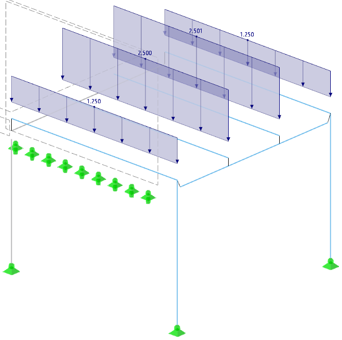
You will notice that the distribution of the loads is no longer correct, as the load is assigned to only some members of the frame girder. Open the Load Wizard by double-clicking either the load or the corresponding item in the "Navigator - Data" (3).
In the "Edit Load Wizard" dialog box, switch to the Geometry tab (1).
Click the
![]() button in the "Remove Influence from" area (2) to add the irrelevant members of the frame girder graphically.
button in the "Remove Influence from" area (2) to add the irrelevant members of the frame girder graphically.
In the work window, select the new members nos. 10 and 11 by clicking them one after another.
Once you click OK, you will return to the dialog box. Close it by clicking OK again. All members of the frame girder are without loads now.
Finally, click the
![]() button to hide the loads again.
button to hide the loads again.












_1.jpg?mw=350&hash=ab2086621f4e50c8c8fb8f3c211a22bc246e0552)


-querkraft-hertha-hurnaus.jpg?mw=350&hash=3306957537863c7a7dc17160e2ced5806b35a7fb)


