The design ratios of the stress-strain analysis are listed in several tables. They are sorted there by specific criteria.
Result Table Manager
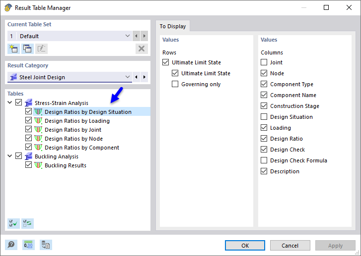
The tables and their details are managed in the "Result Table Manager". Click the
![]() button on the table toolbar to open it (see the Tables for "Design Ratios on Steel Joints" image).
button on the table toolbar to open it (see the Tables for "Design Ratios on Steel Joints" image).
Check to see if the Design Ratios by Design Situations table is activated. If not, select it, as it provides a quick and good overview of the results. The "Buckling Analysis" is selected as well, but it is irrelevant, as the stability design has not been activated for the Ultimate Limit State design configuration.
The "Values" to be displayed for the rows and columns by default are appropriate. Close the dialog box by clicking OK.
Design Ratios of Stress-Strain Analysis
The "Design Ratios by Design Situation" table presents the maximum design ratios of each component type used for the defined steel joints. The values listed in the "Design Check Ratio" column represent the ratios of the existing design values to the respective design resistances.
The table "Design Ratios by Joint" gives an overview of the maximum ratios that were calculated for each type of steel joint. They represent the various design checks of the resistances that were calculated for the plates, fasteners, and welds.
To evaluate the results for every designed node, select the Design Ratios by Node table.
Result Details
In the tables, the results are labeled by check types with numbers. For example, "UL1200.00" represents the fillet weld check. The highest ratio of that design type was calculated for node no. 17. Select that line (1).
To examine the design details of this check, click the
![]() button on the table toolbar (2). The "Design Check Details" window opens.
button on the table toolbar (2). The "Design Check Details" window opens.
This window presents all parameters of the design and the relevant equations. By clicking the
![]() button in the bottom-right area (1), you can switch between values or symbols displayed in the formulas of the design.
button in the bottom-right area (1), you can switch between values or symbols displayed in the formulas of the design.
Select a different weld from the "Component Name" list (2), for example Fin Plate 1 | Plate Cut 1 | Weld (2). The design details are updated so that you can check the stresses of the weld connecting the fin plate and the plate cut.
When you select a different line in the table, the corresponding details are shown. For example, click in the last line to set the bolt check of node no. 23 (if necessary, move the "Design Check Details" window slightly).
Return to the tables by clicking Close.


