You can also evaluate the design results in a specific window. It is useful for checking the detailed result of a node.
Make sure that the Design Ratios by Node table of the "Stress-Strain-Analysis" sub-category is still set. To check the results of the fasteners for node no. 16, click any cell of the second line to select it (1). Then click the
![]() button on the table toolbar (2).
button on the table toolbar (2).
The "Results in Steel Joint" window is opened after a few moments.
Navigator – To Display
In the tree of the "Navigator – To Display" on the left, all components of the connection are listed with their design ratios. Here you can activate or deactivate components individually or in groups for the display.
The forces and moments represent the internal forces applied to the Substitute Steel Joint FE Model. They are related to the ends of the "submodel". Those substitute loads each act at the centers of the members so that they correspond to the internal forces at the x-locations in question.
The equivalent plastic strains displayed on the surfaces are all zero. This means that no part of the plates shows any effects of yielding.
Navigator – Results
Switch to the Navigator – Results (1). The results are organized by specific categories.
Members and Plates
Set the Equivalent stress option (2) to display the equivalent stresses σeqv according to von Mises for the surfaces of the members and plates.
Welds
Clear the Surfaces check box (1). Then activate the Result Sections (2). The equivalent stresses of the welds are displayed. For a better view, you can hide the loads of the submodel by clicking the
![]() button (3).
button (3).
Bolts
Clear the Result Sections check box (1) so that only the forces of the fasteners are displayed. You can check the axial forces and the shear forces of the bolts by selecting the corresponding option in the "Fastener Members" category (2).
The results displayed in the "Results in Steel Joint" window are synchronized with the table. When you select a different table line, the results shown in the window will be updated. Select the results of the Fastener for node no. 21 in the table, for example (1). The results of the steel connection with the grid girder will be shown. Then activate the Surfaces check box again in the "Navigator – Results" (2).
The "Result smoothing" options enable you to control the smoothing of the surfaces and result sections (3). For more details on the smoothing types, see Chapter Result Smoothing of the RFEM manual.
Mesh and Support Forces
Click the
![]() button below the graphic to display the mesh applied to the substitute model (1).
button below the graphic to display the mesh applied to the substitute model (1).
By clicking the
![]() button, you can switch the support reactions on and off. They represent the forces applied to the ends of the substitute model. The
button, you can switch the support reactions on and off. They represent the forces applied to the ends of the substitute model. The
![]() button, in turn, controls the display's internal forces. Activate both buttons (2).
button, in turn, controls the display's internal forces. Activate both buttons (2).
Printing Graphics
The
![]() list button enables you to print the current image. Click its
list button enables you to print the current image. Click its
![]() to open the list, where you select the Print Graphics to Printout Report option (3).
to open the list, where you select the Print Graphics to Printout Report option (3).
The preview of the image is presented with the familiar options to adjust the layout.
Click OK to print the image with the default settings to the printout report without opening it. The "Graphic Printout" window is closed again.
Converting Steel Joint Model to File
Set steel joint type no. 1 again by clicking a line of node no. 16 in the "Design Ratio" table again (see the Opening "Results in Steel Joint" Window image). Then click the
![]() button to save the steel joint model as a separate file.
button to save the steel joint model as a separate file.
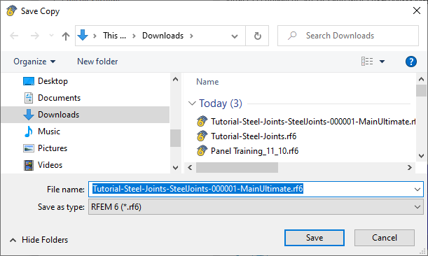
The "Save Copy" dialog box is opened.
Specify the folder and name of the file. Then, click Save to create the *.rf6 file and close the dialog box. Close the "Results in Steel Joint" window, too, by clicking the Close button.
To open the steel joint model file, select the File menu on the RFEM toolbar and click Open (alternatively, use the
![]() button). In the "Open" window, select the *.rf6 file that you have just saved.
button). In the "Open" window, select the *.rf6 file that you have just saved.
Click Open. The Substitute Steel Joint FE Model is opened in a new window of RFEM.
Member plates are modeled by surfaces having a uniform thickness and an isotropic plastic material model. When the surfaces representing parts of the member section cannot be connected directly using their boundary lines, the connection is created by means of "Rigid Links" – for example, when connecting the flanges to the web. The model of fillet welds uses a system of rigid links, too.
The bolt model consists of a system of members, surfaces, and surface contacts. They represent the individual parts of the bolt, shank, head, and nut. A hole is prepared for each bolt in the bolted plates. It is filled with radially arranged members called "Spokes". They have a "Failure if tension" nonlinearity in order to allow only the compressed part of the bolt to act.
The load combinations of the original model are converted to load cases. Thus, the four load cases of the substitute model represent the loading defined in the four load combinations of the total model (see the image Deselecting Combinations for Calculation ). As steel joint type no. 1 includes nodes nos. 16 and 17, there are eight load cases altogether.
Calculate LC1 to determine the results of CO4 for node 16. Click the
![]() button on the toolbar to do so.
button on the toolbar to do so.
As soon as the calculation is finished, you can check the deformations of the substitute model, the stresses and strains of the surfaces, the result sections representing the welds, or the internal forces of the members.
When you have completed reviewing the results, close the substitute model window by selecting File and Close on the menu bar or by clicking the
![]() button next to the "License" box. Do not close the RFEM window, however!
button next to the "License" box. Do not close the RFEM window, however!




.png?mw=350&hash=c6c25b135ffd26af9cd48d77813d2ba5853f936c)




_1.jpg?mw=350&hash=ab2086621f4e50c8c8fb8f3c211a22bc246e0552)


