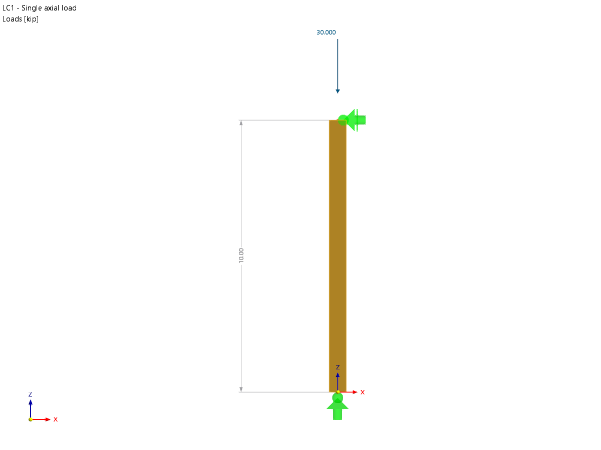
If a member is laterally supported due to a compressive axial force to prevent buckling, it must be ensured that the lateral support is actually able to prevent buckling. Therefore, the aim of this article is to determine the ideal spring stiffness of a lateral support using the Winter model.
KB 001681 | Determination of Ideal Spring Stiffness for Lateral Supports at Buckling Members
Links
Do you have any questions?
If a member is supported laterally to prevent buckling due to a compressive axial force, it must be ensured that the lateral support is actually able to prevent buckling. Therefore, the aim of this article is to determine the ideal spring stiffness of a lateral support using the Winter model.
This technical article analyzes the effects of the connection stiffness on the determination of internal forces, as well as the design of connections using the example of a two-story, double-spanned steel frame.
With the RF-STABILITY and RSBUCK add-on modules for RFEM and RSTAB, it is possible to perform eigenvalue analyses for member structures in order to determine the effective length factors. The effective length coefficients can then be used for the stability design.
Critical load factors and the corresponding mode shapes of any structure can be determined efficiently in RFEM and RSTAB, using the RF-STABILITY or RSBUCK add-on module (linear eigenvalue solver or nonlinear analysis).
- Numerous component types, such as base and end plates, web angles, fin plates, gusset plates, stiffeners, tapers, or ribs for easy input of typical connection situations
- Universally applicable basic components (such as plates, welds, bolts, auxiliary planes) for modeling complex connection situations
- Graphical display of the connection geometry with dynamic updating during the input
- Wide range of cross-section shapes: I-sections, U-sections, angles, T-sections, hollow sections, built-up cross-sections and thin-walled sections
- Library in the Dlubal Center with a large number of program-side template connections, including user-defined templates
- Automatic adaptation of the connection geometry based on the relative arrangement of the components to each other – even in case of subsequent editing of the structural components
In the ultimate configuration of the steel joint design, you have the option to modify the limit plastic strain for welds.
The "Base Plate" component allows you to design base plate connections with cast-in anchors. In this case, plates, welds, anchorages, and steel-concrete interaction are analyzed.
In the "Edit Section" dialog box, you can display the buckling shapes of the Finite Strip Method (FSM) as a 3D graphic.
Recommended Products for You