How may I help you?
Do you have any questions about Dlubal products or need assistance in selecting the right one for your project?
I'm here to help. You can easily reach me through the contact options provided below.
Looking forward to hearing from you!
Amy Heilig, PE
CEO – USA Subsidiary | Sales Engineer


Cutting Patterns of Tensile Membrane Structures
Total items: 4


RF-CUTTING-PATTERN | Features
- Planar and geodesic cutting lines
- Flattening of double-curved surface parts of tensioned membranes or pneumatic cushions
- Definition of cutting patterns by using boundary lines which are not required to be connected
- Sophisticated flattening based on the minimum energy theory
- Welding and boundary allowances
- Uniform or linear compensation in warp and weft direction
- Possibility of different compensations for boundary lines
- Adaptable data organisation (any additional modification of input data is considered up to the final "weld")
- Graphical display of cutting patterns
- Statistical information about each cutting pattern (width, length, size)
- Option to automatically generate cutting patterns from cells

RF-CUTTING-PATTERN | Input
RF-CUTTING-PATTERN is activated by selecting the respective option in the Options tab in General Data of any RFEM model. After activating the add‑on module, a new object, "Cutting Patterns", is displayed under Model Data. If the membrane surface distribution for cutting in the basic position is too large, you can divide the surface by cutting lines (line types "Cut via Two Lines" or "Cut via Section") in the corresponding partial strips.
Then you can define the individual entries for each cutting pattern using the "Cutting Pattern" object. Here you can set boundary lines, compensations, and allowances.
Steps of the working sequence:
- Creation of cutting lines
- Creation of the pattern by selecting its boundary lines or using a semi‑automatic generator
- Free selection of warp and weft orientation by entering an angle
- Application of compensation values
- Optional definition of different compensations for boundary lines
- Different allowances (welding, boundary line)
- Preliminary representation of the cutting pattern in the graphic window at the side without starting the main nonlinear calculation
RF-CUTTING-PATTERN | Calculation
The nonlinear calculation adopts the real mesh geometry of planar, buckled, simple curved, or double curved surface components from the selected cutting pattern and flattens this surface component in compliance with the minimization of distortion energy, assuming defined material behavior.
In simplified terms, this method attempts to compress the mesh geometry in a press, assuming frictionless contact, and to find the state in which the stresses from flattening in the component are in equilibrium in the plane. This way, minimum energy and optimum accuracy of the cutting pattern are achieved. Compensation for warp and weft as well as compensation for boundary lines are considered. Then, the defined allowances on boundary lines are applied to the resulting planar surface geometry.
Features:
- Minimization of distortion energy in the flattening process for very accurate cutting patterns
- Application for almost all mesh arrangements
- Recognition of adjacent cutting pattern definitions to keep the same length
- Mesh application for main calculation

RF-CUTTING-PATTERN | Results
After the calculation, the "Point Coordinates" tab appears in the cutting pattern dialog box. In this tab, the result is displayed in the form of a table with coordinates and a surface in the graphical window. The coordinate table presents new flattened coordinates relative to the centroid of the cutting pattern for each mesh node. Furthermore, the cutting pattern with the coordinate system at the centroid is represented in the graphical window. When selecting a table cell, the respective node is displayed with an arrow in the graphic. In addition, the area of the cutting pattern is displayed below the node table.
Moreover, standard stress/strain results for each pattern are displayed in the RF‑CUTTING‑PATTERN load case in RFEM.
Features:
- Results in a table, including information about the cutting pattern
- Smart table relating to the graphic
- Results of flattened geometry in a DXF file
- Output of strains after flattening in order to evaluate the cutting patterns
- Results of strains after flattening for the evaluation of patterns

.png?mw=192&hash=f63e4a3f1836233005de32f60201d5392e507cf1)
Calculate Your Price
Total Amount 2,820.00 USD
The price is valid for United States.


Implemented Standards for Reinforced Concrete Design
Standards for Concrete Design
Annexes for EN 1992-1-1


Duration: 01:10:25 min

Duration: 00:49:22 min
.png?mw=350&hash=c6c25b135ffd26af9cd48d77813d2ba5853f936c)
Duration: 00:02:51 min

Duration: 00:00:46 min

Duration: 00:00:41 min

Duration: 00:00:59 min

Duration: 00:00:56 min

Duration: 00:53:57 min

Duration: 01:05:10 min


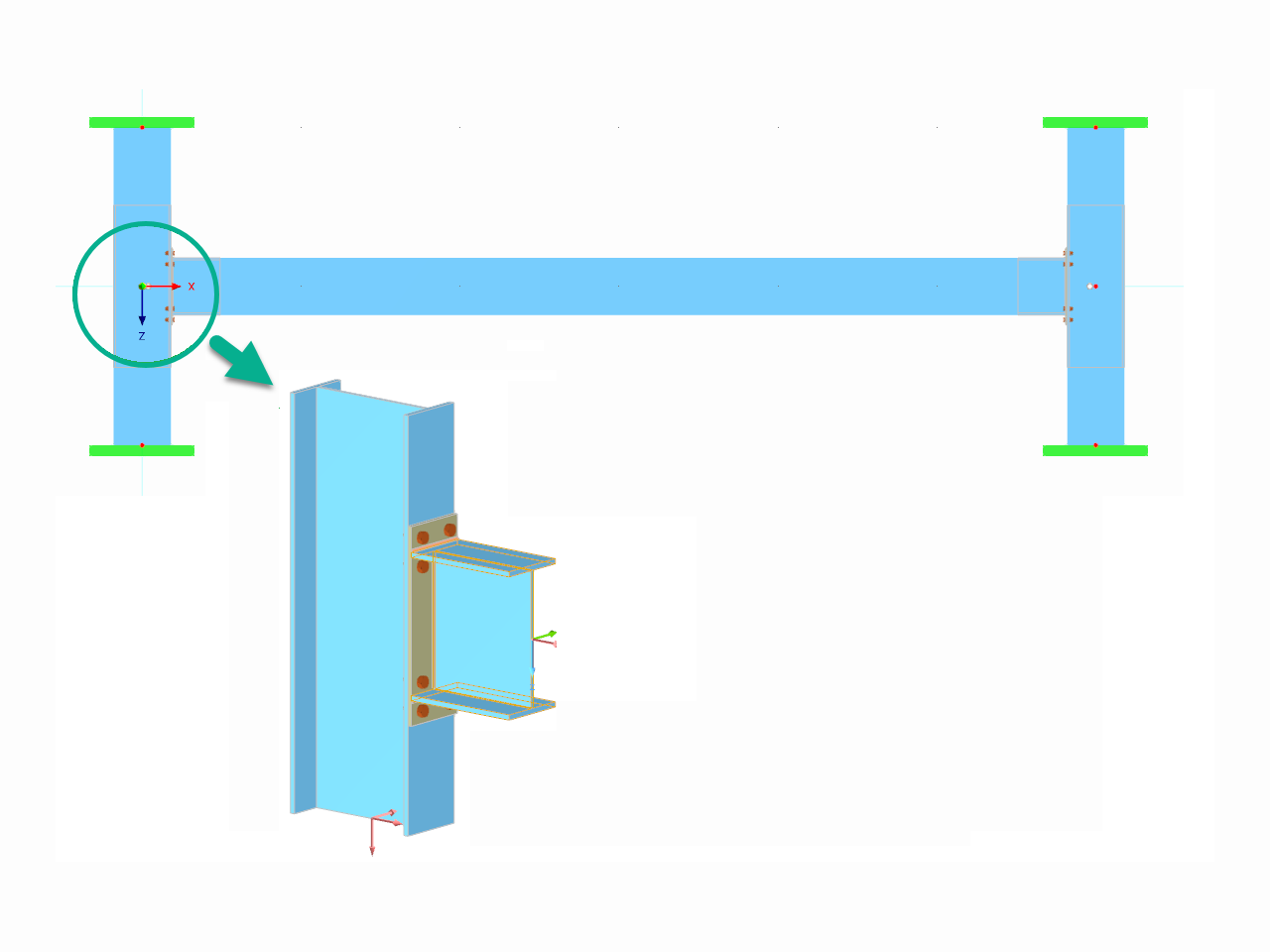
This article explores the importance of considering joint-structure interaction in modeling and design and how to do it in RFEM 6.
.png?mw=512&hash=4a84cbc5b1eacf1afb4217e8e43c5cb50ed8d827)
This article provides a comprehensive overview of essential seismic analysis methods, explaining their principles and applications, as well as the scenarios in which they are most effective

The weld stresses between surfaces can be determined using the Stress-Strain Analysis add-on in RFEM 6. Furthermore, the stress limit determined according to the applicable standard can be input to determine the stress ratio of the weld. This article focuses on the fillet weld design according to AISC 360-22 [1] with two examples from AISC Volume 1: Design Examples [2].
This article demonstrates how to initiate and conduct the analysis in the software, followed by a short discussion of the underlying concept.


Want to automatically consider steel joint stiffness in your global RFEM model? Utilize the Steel Joints add-on!
Activate joint-structure interaction in the stiffness analysis of your steel joints. Hinges with springs are then automatically generated in the global model and included in subsequent calculations.
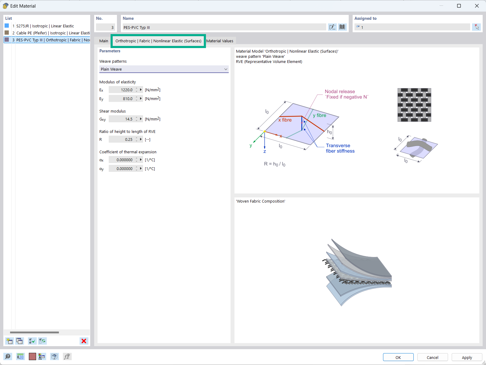
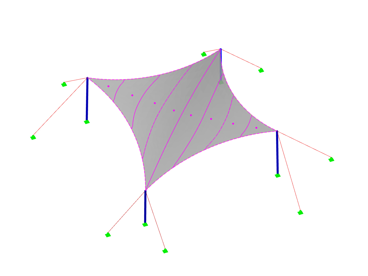
The "Orthotropic | Fabric | Nonlinear Elastic (Surfaces)" material model allows you to define prestressed fabric membranes using the representative microstructure-solid element model – RVE.
By considering the fabric geometry in the microstructure model, the corresponding transversal strain effect can now be considered for all force conditions in the membrane.
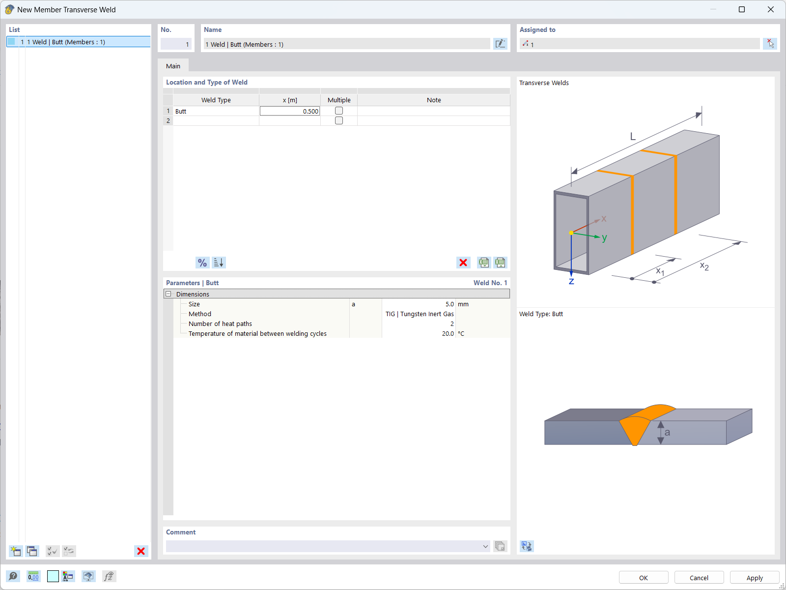
In the Aluminum Design add-on, you can consider the localized strength reduction in the HAZ due to transverse welds when performing design according to EN 1999-1-1.
Moreover, the Effective Sections add-on in RSECTION allows you to calculate the effective cross-section according to EN 1999-1-1, taking into account the transverse weld.

In the ultimate configuration of the steel joint design, you have the option to modify the limit plastic strain for welds.
I would like to analyze temporary structures. Which programs do you recommend?
Which Dlubal programs do I need for tensile membrane structures?
I would like to analyze cable and tensile structures. Is it possible to use RFEM or RSTAB for this?
In the Steel Joints add-on, I get high utilization ratios for preloaded bolts in the tension design. Where do these high utilization ratios come from and how can I evaluate the load-bearing reserves of the bolt?
How can I fix the error warning “10060 - The structure is unstable” for modal analysis instability?
How can treating a connection as fully rigid result in an uneconomical design?


_1.jpg?mw=350&hash=ab2086621f4e50c8c8fb8f3c211a22bc246e0552)


