- Applicable for members defined as sets of members
- Separate solver that considers 7 deformation directions (ux, uy, uz, φx, φy, φz, ω) or 8 internal forces (N, Vu, Vv, Mt,pri, Mt,sec, Mu, Mv, Mω)
- Nonlinear design according to second-order analysis
- Input of imperfections
- Calculation of critical load factors and buckling mode shapes as well as the visualization of them (incl. warping)
- Integration into member design in the RF-/STEEL AISC and RF‑/STEEL EC3 add‑on modules
- Available for all thin‑walled steel cross‑sections
RF-/STEEL Warping Torsion | Features


Duration: 00:51:43 min
Duration: 00:50:35 min
Duration: 00:53:19 min

Duration: 00:50:11 min

Duration: 00:58:55 min

Duration: 01:09:22 min

Duration: 00:58:13 min

Duration: 00:59:06 min

Duration: 01:01:07 min


.png?mw=350&hash=d538a044ed58714e93ef2f2fb0fe731b25e855ee)


This article provides a detailed overview of the import features from RFEM 6 and RSTAB 9 to AutoCAD/DXF files.
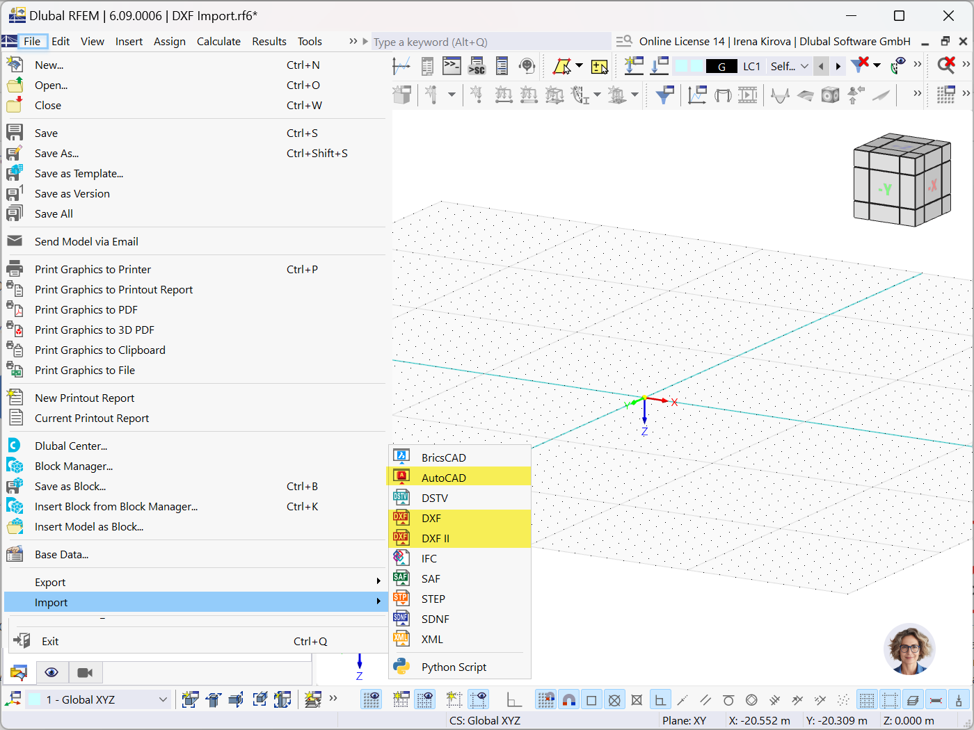
This article outlines the data exchange capabilities between RFEM 6 / RSTAB 9 and AutoCAD, focusing on DXF file integration.

This article provides a detailed overview of the export features from RFEM 6 and RSTAB 9 to AutoCAD/DXF files, including options for exporting dimensions, FE meshes, and deformed shapes.

The browser plugin Boomerang as well as the API testing program SoapUI are both useful tools to quickly check our WebService functions. With their assistance, it becomes effortless to identify available classes and their respective parameters. This article aims to serve as a comprehensive guide on effectively utilizing Boomerang and SoapUI in conjunction with the Dlubal WebService.
.jpg?mw=350&hash=7ecb25ca2a1442e4f8137ff368d300efd3534e28)


Using the direct interface of RFEM 6 / RSTAB 9 with BricsCAD, you can import and export nodes and lines.
Furthermore, you can export different objects (for example, cross-sections) from RFEM 6 / RSTAB 9 to separate layers in BricksCAD.
Further features include the export of a deformed FE mesh and dimension lines.

The DSTV product interface for steel structures is available in RFEM 6 / RSTAB 9 for transferring pure member structures (including loads, load cases, load combinations, imperfections).
The DSTV interface allows you to exchange data between RFEM 6 / RSTAB 9 and the programs like "Bentley ProStructure 3D", "Tekla Structures", "Bocad", "Intergraph Frameworks", "Graitec Advance Steel", "Cadwork", and many others.
Using the SDNF interface, you can import and export data such as materials, cross-sections, members, and surfaces in RFEM 6 and RSTAB 9. It allows you to exchange the file-based data with programs such as Tekla Structures or Advance Steel.

The DXF II interface is based on a different technology than the DXF interface. It provides additional features, such as the export of deformed meshes, the export of dimension lines, and so on.
How can I exchange data between RFEM 6 / RSTAB 9 and IDEA StatiCa?
How can I export or import an IFC file in RFEM 6 / RSTAB 9?
The cross-sections from my imported IFC file are not converted correctly.
Is Revit Add-in installed automatically in RFEM 6?
How can I define RSECTION cross-sections in Grasshopper?
Which interfaces are available for the data exchange between RFEM 6 and HiCAD?


-querkraft-hertha-hurnaus.jpg?mw=350&hash=3306957537863c7a7dc17160e2ced5806b35a7fb)


Recommended Products for You
RFEM 6 | Main Program RFEM 6

The new generation of 3D FEA software is used for the structural analysis of members, surfaces, and solids.
Price of First License
4,790.00 USD
RFEM 6 | Special Solutions

The Building Model add-on for RFEM allows you to define and manipulate a building using stories. The stories can be adjusted in many ways afterwards. The information about stories and the entire model (center of gravity) is displayed in tables and graphics.
Price of First License
1,970.00 USD
RFEM 6 | Additional Analysis

The Form-Finding add-on finds the optimal shape of members subjected to axial forces and tension-loaded surface models. The shape is determined by the equilibrium between the member axial force or the membrane stress and the existing boundary conditions.
Price of First License
2,320.00 USD
RFEM 6 | Design

The Masonry Design add-on for RFEM allows you to design masonry using the finite element method. It was developed as part of the research project titled DDMaS – Digitizing the Design of Masonry Structures. The material model represents the nonlinear behavior of the brick-mortar combination in the form of macro-modeling.
Price of First License
1,860.00 USD
RFEM 6 | Design

The Steel Design add-on performs the ultimate and serviceability limit state design checks of steel members according to various standards.
Price of First License
2,970.00 USD
RFEM 6 | Design

The Timber Design add-on performs the ultimate, serviceability, and fire resistance limit state design checks of timber members according to various standards.
Price of First License
2,170.00 USD
RFEM 6 | Special Solutions

The Multilayer Surfaces add-on allows you to define multilayer surface structures. The calculation can be carried out with or without the shear coupling.
Price of First License
1,560.00 USD
RFEM 6 | Design

The Aluminum Design add-on performs the ultimate and serviceability limit state design checks of aluminum members according to various standards.
Price of First License
1,970.00 USD
RFEM 6 | Joints
.png?mw=600&hash=49b6a289915d28aa461360f7308b092631b1446e)
The Steel Joints add-on for RFEM allows you to analyze steel connections using an FE model. The FE model is generated automatically in the background and can be controlled via the simple and familiar input of components.
Price of First License
2,670.00 USD
RFEM 6 | Design

With the Concrete Foundations add-on, you can design square and rectangular individual foundations. In addition to the reinforced concrete design, geotechnical verifications are also carried out. You also determine automatic reinforcement suggestions and receive detailed reinforcement plans and 3D renderings of the foundation structures.
Price of First License
1,260.00 USD
RFEM 6 | Design

The Concrete Design add-on allows for various design checks according to international standards. You can design members, surfaces, and columns, as well as perform punching and deformation analyses.
Price of First License
2,970.00 USD
RSTAB 9 | Main Program RSTAB 9

The modern 3D structural analysis and design program is suitable for the structural and dynamic analysis of beam structures as well as the design of concrete, steel, timber, and other materials.
Price of First License
3,380.00 USD
RSTAB 9 | Design
Concrete Design add-on allows for various design checks of members and columns according to international standards.
Price of First License
2,970.00 USD
RSTAB 9 | Design
The Steel Design add-on performs the ultimate and serviceability limit state design checks of steel members according to various standards.
Price of First License
2,970.00 USD
RSTAB 9 | Design
The Timber Design add-on performs the ultimate, serviceability, and fire resistance limit state design checks of timber members according to various standards.
Price of First License
2,170.00 USD
RSTAB 9 | Design
The Aluminum Design add-on performs the ultimate and serviceability limit state design checks of aluminum members according to various standards.
Price of First License
1,970.00 USD
RSTAB 9 | Design
Concrete Foundations for RSTAB 9

With the Concrete Foundations add-on, you can design square and rectangular individual foundations. In addition to the reinforced concrete design, geotechnical verifications are also carried out. You also determine automatic reinforcement suggestions and receive detailed reinforcement plans and 3D renderings of the foundation structures.
Price of First License
1,260.00 USD
RSTAB 9 | Special Solutions

The two-part Optimization & Costs / CO2 Emission Estimation add-on finds suitable parameters for parameterized models and blocks via the artificial intelligence (AI) technique of particle swarm optimization (PSO) for compliance with common optimization criteria. Furthermore, this add-on estimates the model costs or CO2 emissions by specifying unit costs or emissions per material definition for the structural model.
Price of First License
1,660.00 USD
RFEM 6 | Special Solutions
The two-part Optimization & Costs / CO2 Emission Estimation add-on finds suitable parameters for parameterized models and blocks via the artificial intelligence (AI) technique of particle swarm optimization (PSO) for compliance with common optimization criteria. Furthermore, this add-on estimates the model costs or CO2 emissions by specifying unit costs or emissions per material definition for the structural model.
Price of First License
1,660.00 USD