This chapter explains how to create line welded joints. For this purpose, an additional plate is inserted into the model, to which the splice is welded. Since the welded joint cannot be attached to a surface without a thickness - that is, directly to the solid - it is necessary to create additional surfaces between the solid and the coupling plate.
Modeling Connecting Surfaces
Copy the back plate of the splice by -2 cm in the X-direction and enlarge it by dragging and dropping the corners outwards 2 cm.
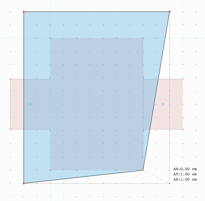
Now select the lines at the edge of the boundary surface of the solid and copy them by -2 cm as well. Activate the step link in the "Numbering and Options" tab and specify in the corresponding tab that the lines are to be connected to surfaces. You can now model the line welded joint between these surfaces and the connecting plate.


Creating Line Welded Joints
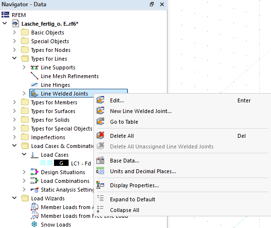
You can create a new line welded joint under "Types for Lines" in the navigator.
You can select various joint and weld types, and define additional parameters, depending on your selection. The joint type is shown graphically on the right of the dialog box.
In the webinar, a tee joint with the "Fillet Weld" type was used.

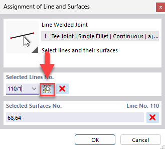
When you assign the line welded joint in the graphic, you must first select the line along which the line welded joint runs. Then, select the surface to be connected as well as the connecting plate. Use the
![]() button to assign the next line welded joint.
button to assign the next line welded joint.
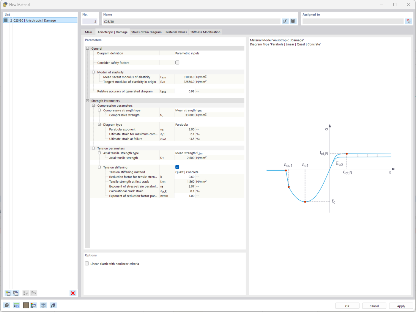
In the "Stress-Strain Analysis - Configuration" tab, you can edit and assign the "Line Welded Joint Configuration". In the configuration, select the stresses to be calculated and specify the limit stresses. To specify user-defined limit stress, select the "User" limit stress type. Thus, the "User-Defined Limit Stress [N/mm²]" text box is activated.


.png?mw=512&hash=4a84cbc5b1eacf1afb4217e8e43c5cb50ed8d827)


_1.jpg?mw=350&hash=ab2086621f4e50c8c8fb8f3c211a22bc246e0552)


-querkraft-hertha-hurnaus.jpg?mw=350&hash=3306957537863c7a7dc17160e2ced5806b35a7fb)


