This section explains how you can subtract a given solid from an existing solid. The "Hole" solid type provides you with this possibility. In the webinar, a cuboid with this solid type was created and a notch was generated in the middle of the splice.
To create the cuboid, adjust the work plane first.
Use the
![]() button to copy the top left corner of the structure by -2 cm in the Z-direction. In particular, make sure that the "Create Copy" option is activated. Then, set this point as the grid origin and rotate the grid in the XY plane.
button to copy the top left corner of the structure by -2 cm in the Z-direction. In particular, make sure that the "Create Copy" option is activated. Then, set this point as the grid origin and rotate the grid in the XY plane.
Tip
Use the
![]() button to move the origin of the grid plane in the graphic.
button to move the origin of the grid plane in the graphic.

Tip
You can use the options of the
![]() button to show or hide the selected objects or to cancel the visibility mode.
button to show or hide the selected objects or to cancel the visibility mode.
Now, create a rectangular surface between the points [X: 5 m / Y: 5 m / Z: -12 m] and [X: 18 m / Y: 2 m / Z: -12 m]. To do this, it may be useful to hide the solid. Extrude the rectangular surface 20 cm, so the splice is cut across the entire height of the cuboid. The previous chapter explains how to extrude a surface.

Double-click the cuboid to open the editing dialog box. Select Hole solid type. Click "OK" to confirm; a message will appear saying that the action may lead to the repeated creation of solids. If you confirm this, a new solid is generated, which corresponds to the splice without the intersection with the cuboid.

Cancel the generated state of the new solid using the
![]() button in the editing dialog box and confirming the information that appears.
button in the editing dialog box and confirming the information that appears.

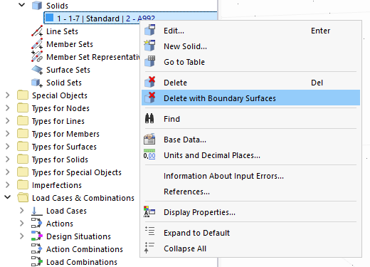
The hole solid type can be removed now. To do this, use the "Delete with Boundary Surfaces" function.


_1.jpg?mw=350&hash=ab2086621f4e50c8c8fb8f3c211a22bc246e0552)


-querkraft-hertha-hurnaus.jpg?mw=350&hash=3306957537863c7a7dc17160e2ced5806b35a7fb)


