In RFEM 6 and the corresponding Steel Joints add-on, it is possible to consider circular hollow sections. These types of sections undergo thorough analysis using the state-of-the-art segmentation method in the steel joint submodel. Hence, you can easily tweak and customize the segmentation settings in the Steel Joint configuration to your exact requirements.
With the ability to model circular hollow sections, many connections from the steel design can now be created in the Steel Joints add-on. These include, for example, welded truss connections with a flat chord connection plane, connections of the same type with a stiffening gusset plate, bolted end plate connections, CHS-to-CHS front-to-side connections, and so on. (Image 01).

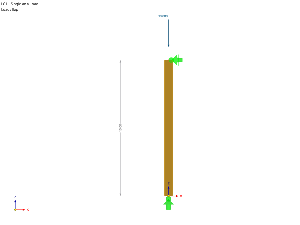
In this article, you will learn how to create one of these connections; namely, a bolted end plate connection will be modeled using a practical example. The creation of this connection type is applied to the steel connection between the members of the steel frame truss shown in Image 02.

First, you need to know that in RFEM 6 you can model steel connections in the "New Steel Joint" window. Please note that this is only possible if the Steel Joints add-on has been activated in the "Base Data" beforehand. The "New Steel Joint" window can be opened by right-clicking on the node to which the joint is to be assigned or via the Data navigator (Image 03).

Either way, the “New Steel Joint” window will open as shown in Image 04. Note that if you open the window through the Data navigator, you need to specify the node intended for modeling and design in the “Assigned to Node” section. As soon as you assign a design node (that is, node No. 101 in this model), the program assigns all the members associated with the node and groups them into separate groups (Image 04).

In this way, members with identical properties are grouped so that you can see these groupings in the “Members” tab as well (Image 05). This tab manages the detailed settings of the members associated with the node, such as their type ("ended" or "continuous") and form of support.

However, the most interesting tab for this article is the “Components” tab, where the components are added and thus the connection is modeled. Here you can add the desired components at the beginning and/or end of the list by simply selecting them in the “Select Component” window, as shown in Image 06. As the image shows, the first component that needs to be selected for the connection of interest is the “Plate to Plate” component.

To correctly create the end plate connection, the settings of the component must be adjusted. For example, in the "Plate" section, plate properties such as material, thickness, width, length, and offsets can be redefined. For this component, the properties are defined as shown in Image 07. The welds are set to "Fillet weld – front side" with a dimension of 5 mm and the number of bolts is set to zero, but this is only because the bolts will be aligned later.

Next, you want to change the shape of the plate from rectangular to round. To do this, you need to add the “Plate Editor” (Image 08), which can be selected in the same way as previously shown for the “Plate to Plate” component.

In the “Plate Editor” component, the modification settings now include selecting the plate to modify (in this case, Plate 1) and the type of operation to apply. Since you want to round the plate, the latter is set to “Rounding” with a radius of 200 mm (half of the plate dimension), which is set in the “Rounding Settings” section (Image 09).

Please note that the connection consists of two plates, so you need to add another plate editor for Plate 2. Alternatively, you can simply copy the "Plate Editor" component you just defined by right-clicking on it and selecting "Copy Components below" (Image 10). Once the component is copied, you need to change the settings and define Plate 2 as the plate to be modified (Image 11).


Finally, one last component must be added for modeling the end plate connection; namely, the "Fasteners". This component can be inserted into the components list in the same way as the other components used so far (Image 12).

Image 13 shows you the fastener settings that need to be adjusted to properly model the end plate connection. In addition to defining Plates 1 and 2 as components to be connected (in the “To Connect” section), you need to define and arrange the bolts properly. This includes setting the diameter of the bolts, the arrangement pattern (which can be orthogonal, polar, or defined by coordinates), the radius in which the bolts should be arranged, their number, and the angles between them, as well as considering whether the bolts are preloaded or not and whether the shear plane is in the thread. As the image shows, eight M16 bolts are defined as polar with a radius of 160 mm and an angle of 45 degrees between each of them.

The connection is now modeled and can be examined in detail by opening the real view. This is done by right-clicking on the preview of the connection in the right-hand part of the dialog window and selecting the option "Open real view" (Image 14).


Webinar | Connections with Circular Hollow Sections in RFEM 6


.png?mw=350&hash=c6c25b135ffd26af9cd48d77813d2ba5853f936c)


_1.jpg?mw=350&hash=ab2086621f4e50c8c8fb8f3c211a22bc246e0552)


