In EN 1993-1-1, the General Method was introduced as a design format for stability designs, which can be used for planar systems with any boundary conditions and variable structural height. The design checks can be performed for loading in the main load-bearing plane and simultaneous compression. The stability cases of lateral-torsional buckling and flexural buckling are analyzed from the main supporting plane, that is, about the structural component's weak axis. Therefore, the question often arises how to design in this context flexural buckling in the main load-bearing plane.
KB 000868 | General Method for Stability Analyses According to EN 1993-1-1 and Buckling in...


At first, the governing joint designs are arranged in groups and displayed with the basic geometry of the joint in the first result window. In the other result windows, you can see all fundamental design details.
Dimensions, material properties, and welds important for the connection construction are displayed immediately and can be printed directly. Similarly, export to DXF-file is enabled. The connections can be visualized in the RF-/JOINTS Timber - Timber to Timber module as well as in RFEM/RSTAB.
All graphics can be included in the RFEM/RSTAB printout report or printed directly. Due to the scaled output, an optimal visual check is possible as early as in the design phase.

First, select the joint type and the design standard.
The connected members are imported from the RFEM/RSTAB model. The add-on module automatically checks if all geometry conditions are fulfilled.
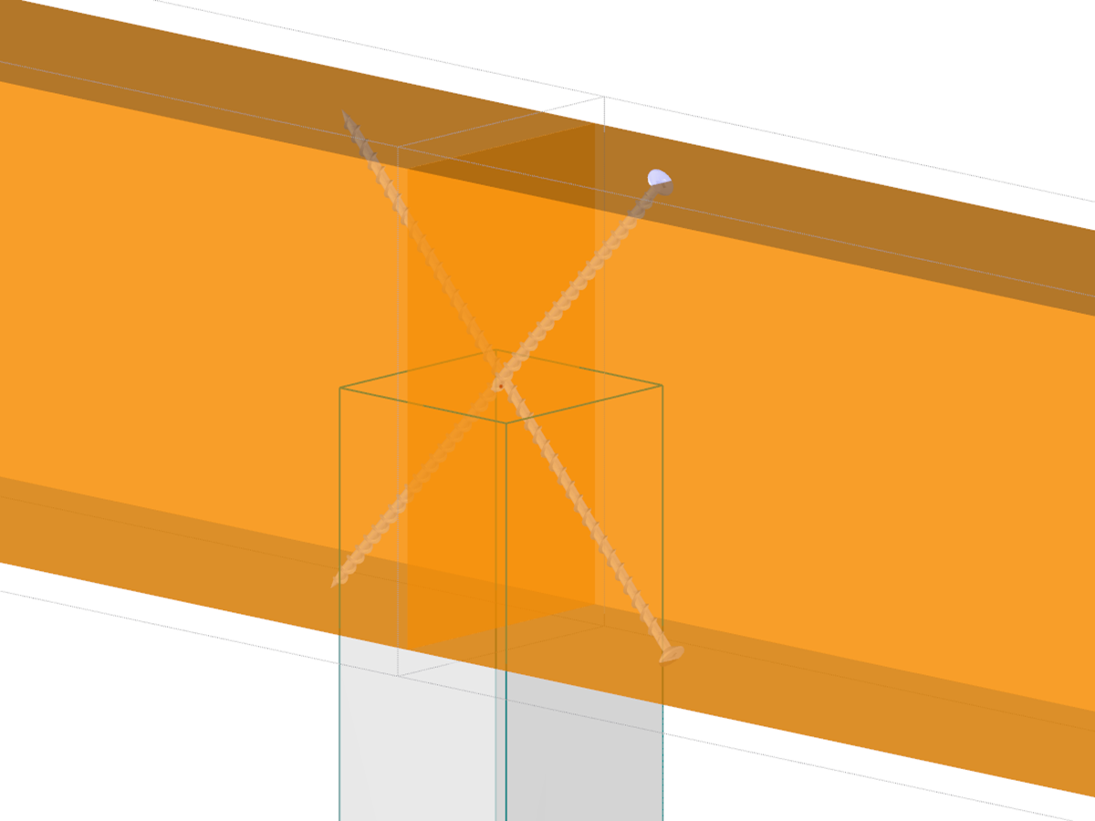
In addition, the loads are imported automatically from RFEM/RSTAB. In the Geometry window, you can specify the screw parameters (diameter, length, angle, and so on).
.png?mw=512&hash=8c5302ae04d7a2024cab77b7f047eafc1f238334)
- Design of hinged connections
- Biaxial inclination of the connected member (for example, a jack rafter joint)
- Connection of any number of members on one node for the type "Main member only"
- Screw diameter 6 mm – 12 mm
- Automatic check of the minimum distance between screws
- Optional free definition of screw distances
- Transfer of eccentricity from RFEM/RSTAB
- Crosswise or parallel screw alignment
- Definition of up to 16 screws in a row
- Graphical visualization of joints in the add-on module and in RFEM/RSTAB
- Performing all required designs

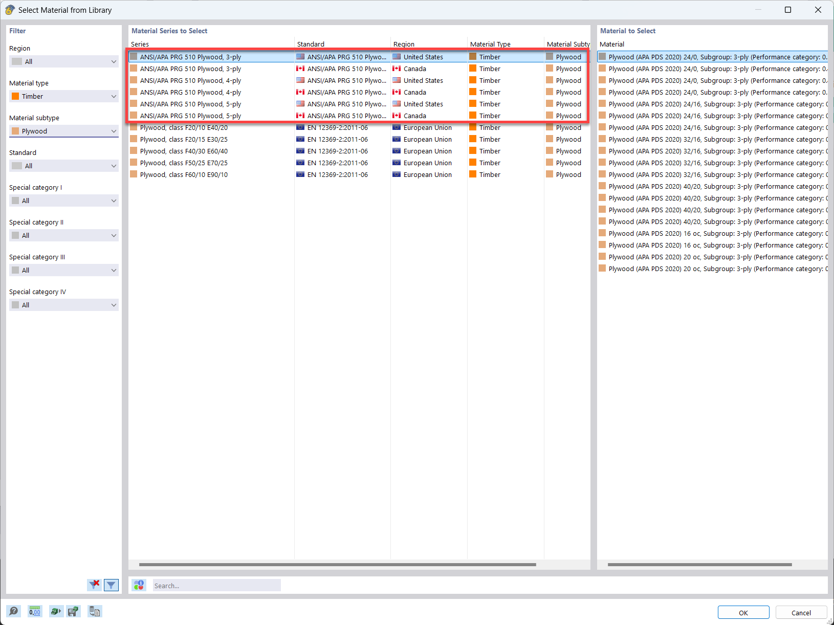
In the material library of RFEM, you can find plywood materials according to the US and Canadian standards ANSI/APA PRG 510 Plywood (USA/CAN).
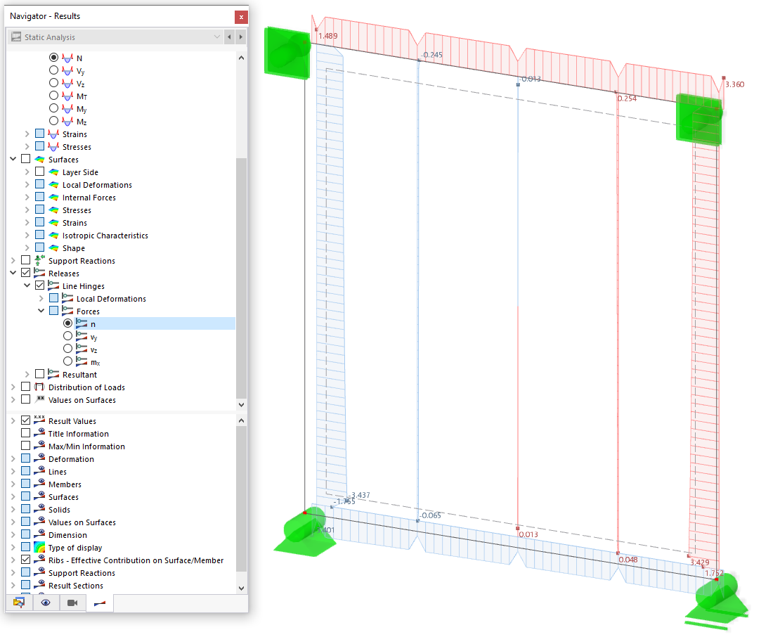
Do I need to add a line hinge/line release for the CLT wall-to-floor connection in the Building Model add-on?


.png?mw=600&hash=49b6a289915d28aa461360f7308b092631b1446e)