Question
Why it is not possible to design a biaxial bending with the RF‑/JOINTS add-on module?
Answer:
In the current standards, fasteners or connections are always designed in one plane only. The reason for this is that the design checks of shear and so on can only be analyzed in a 2D plane. The design of bearing, for example, is not possible for a failure out of the plane.
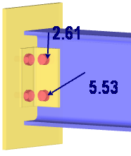
Since internal forces in vy and vz can always occur in a three-dimensional calculation, it has been proven useful in practice to allow a small proportion of internal forces in the secondary direction and not to fully utilize the connection. However, if the ratio of the shear force in the secondary direction is too high, a detailed analysis with an FE simulation might be necessary.
- Add-on Modules
- RF-JOINTS Timber | Timber to Timber 5
- RF-JOINTS Timber | Steel to Timber 5
- RF-JOINTS Steel | Rigid 5
- RF-JOINTS Steel | DSTV 5
- RF-JOINTS Steel | Pinned 5
- RF-JOINTS Steel | Tower 5
- Steel Structures
- Timber Structures
- Finite Element Analysis
- Steel Connections
- Timber Connections
- Eurocode 5
- Eurocode 3
Do you have any questions?
![Timber Panel Wall Stiffnesses](/en/webimage/049956/3893282/49956.png?mw=512&hash=8dfc2b6d0af6ade74073e21655c6a73a34a77751)
In this article, the calculation of a timber panel wall with the beam panel thickness type is compared with a manual calculation.
![KB 001848 | Timber Column Design as per the 2018 NDS Standard in RFEM 6](/en/webimage/040983/3525158/Timber_Column_for_KB_1848.png?mw=512&hash=8767c3300658d77c253bb7ff632327937a04dd95)
Using the Timber Design add-on, timber column design is possible according to the 2018 NDS standard ASD method. Accurately calculating timber member compressive capacity and adjustment factors is important for safety considerations and design. The following article will verify the maximum critical buckling strength calculated by the Timber Design add-on using step-by-step analytical equations as per the NDS 2018 standard including the compressive adjustment factors, adjusted compressive design value, and final design ratio.
![KB 001875 | AISC 341-22 Moment Frame Member Design in RFEM 6](/en/webimage/047794/3736755/im01.jpg?mw=512&hash=33697d419a0e8a96b738e8e2e97fae057743a108)
The three types of moment frames (Ordinary, Intermediate, Special) are available in the Steel Design add-on of RFEM 6. The seismic design result according to AISC 341-22 is categorized into two sections: member requirements and connection requirements.
![KB 001761 | ...](/en/webimage/034236/3383734/Image_1.png?mw=512&hash=e291c1e4af5953551bde5d9d71f599f36ae2e3f7)
The Steel Design add-on in RFEM 6 now offers the ability to perform seismic design according to AISC 341-16 and AISC 341-22. Five types of seismic force-resisting systems (SFRS) are currently available.
![Feature 002824 | OSB Material for USA and Canada](/en/webimage/050460/3955503/2024-06-28_10-42-39.png?mw=512&hash=5ec86ff7955d8c9a50e53301df3f21fceda009a5)
In RFEM, the oriented strand board (OSB) material is available for the USA and Canada. The material parameters are taken from the "Panel Design Specification manual".
![Feature 002820 | Limit Plastic Strain for Welds](/en/webimage/050344/3881226/1.png?mw=512&hash=9d7f6c198b6d4ae6ee8f2fa8bca75f85579e14c9)
In the ultimate configuration of the steel joint design, you have the option to modify the limit plastic strain for welds.
![Component "Base Plate"](/en/webimage/050345/3936120/50345.png?mw=512&hash=3bd641cb1a2445804b338855e4debfc40c6563e9)
The "Base Plate" component allows you to design base plate connections with cast-in anchors. In this case, plates, welds, anchorages, and steel-concrete interaction are analyzed.
![Feature 002807 | 3D Display of FSM Results](/en/webimage/049281/3861162/2024-05-01_10-32-55.png?mw=512&hash=2377d291bc20ac3d78d617b50c131614e99ac6f7)
In the "Edit Section" dialog box, you can display the buckling shapes of the Finite Strip Method (FSM) as a 3D graphic.
Recommended Products for You