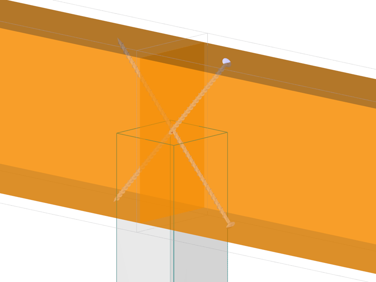
- Design of hinged connections
- Biaxial inclination of the connected member (for example, a jack rafter joint)
- Connection of any number of members on one node for the "Main member only" type
- Screw diameter 6 mm – 12 mm
- Automatic check of the minimum distance between screws
- Optional free definition of screw distances
- Transfer of eccentricity from RFEM/RSTAB
- Crosswise or parallel screw alignment
- Definition of up to 16 screws in a row
- Graphical visualization of joints in the add-on module and in RFEM/RSTAB
- Performing all required designs
RF-/JOINTS TIMBER - Timber to Timber | Features
.png?mw=1024&hash=7c424b9b75f951cc6b40e414ba09ed21ca789737)


Duration: 00:01:40 min

Duration: 00:05:55 min

Duration: 03:02:13 min

Duration: 03:02:42 min

Duration: 02:37:08 min

Duration: 00:02:14 min

Duration: 02:53:48 min

Duration: 01:08:50 min

Duration: 01:08:19 min


Dlubal_KohlA_]_LI.jpg?mw=350&hash=21d94ec9a723c608496e9e95a21bb1309ab5067a)


For structural dimensioning according to the valid rules, there are often several options or calculation methods to determine the internal forces. It is up to the engineer to decide which theory is suitable for designing the structure.

Critical load factors and the corresponding mode shapes of any structure can be determined efficiently in RFEM and RSTAB, using the RF-STABILITY or RSBUCK add-on module (linear eigenvalue solver or nonlinear analysis).

For reinforced concrete components and structures whose structural behavior is significantly influenced by the second-order effects, Eurocode 2 provides the general method based on a nonlinear determination of internal forces according to the second-order analysis (5.8.6), as well as an approximation method based on the nominal curvature (5.8.8).
The aim of this technical article is to perform a design according to the general design method of Eurocode 2, using the example of a slender reinforced concrete column.
The aim of this technical article is to perform a design according to the general design method of Eurocode 2, using the example of a slender reinforced concrete column.

This technical article addresses the direct deformation analysis of reinforced concrete beams considering the long-term effects of creep and shrinkage. The direct calculation according to Eurocode 2 (EN 1992-1-1, Section 7.4.3) is explained using a single-span beam. Particular emphasis is placed on tension stiffening, behavior in the cracked state based on the distribution factor (damage parameter), and consideration of shrinkage and creep behavior.


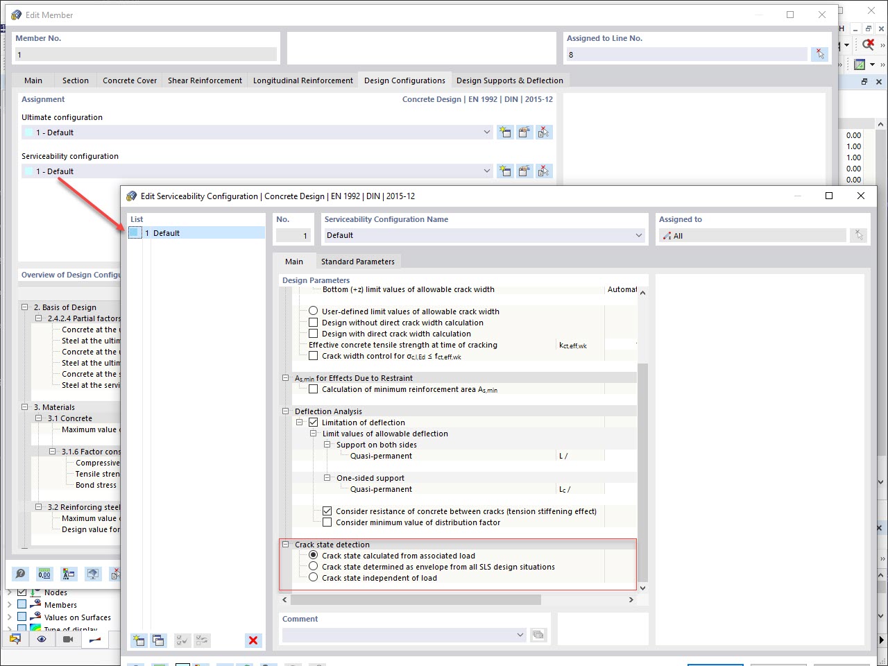
Various design parameters of the cross-sections can be adjusted in the serviceability limit state configuration. The applied cross-section condition for the deformation and crack width analysis can be controlled there.
For this, the following settings can be activated:
- Crack state calculated from associated load
- Crack state determined as an envelope from all SLS design situations
- Cracked state of cross-section - independent of load
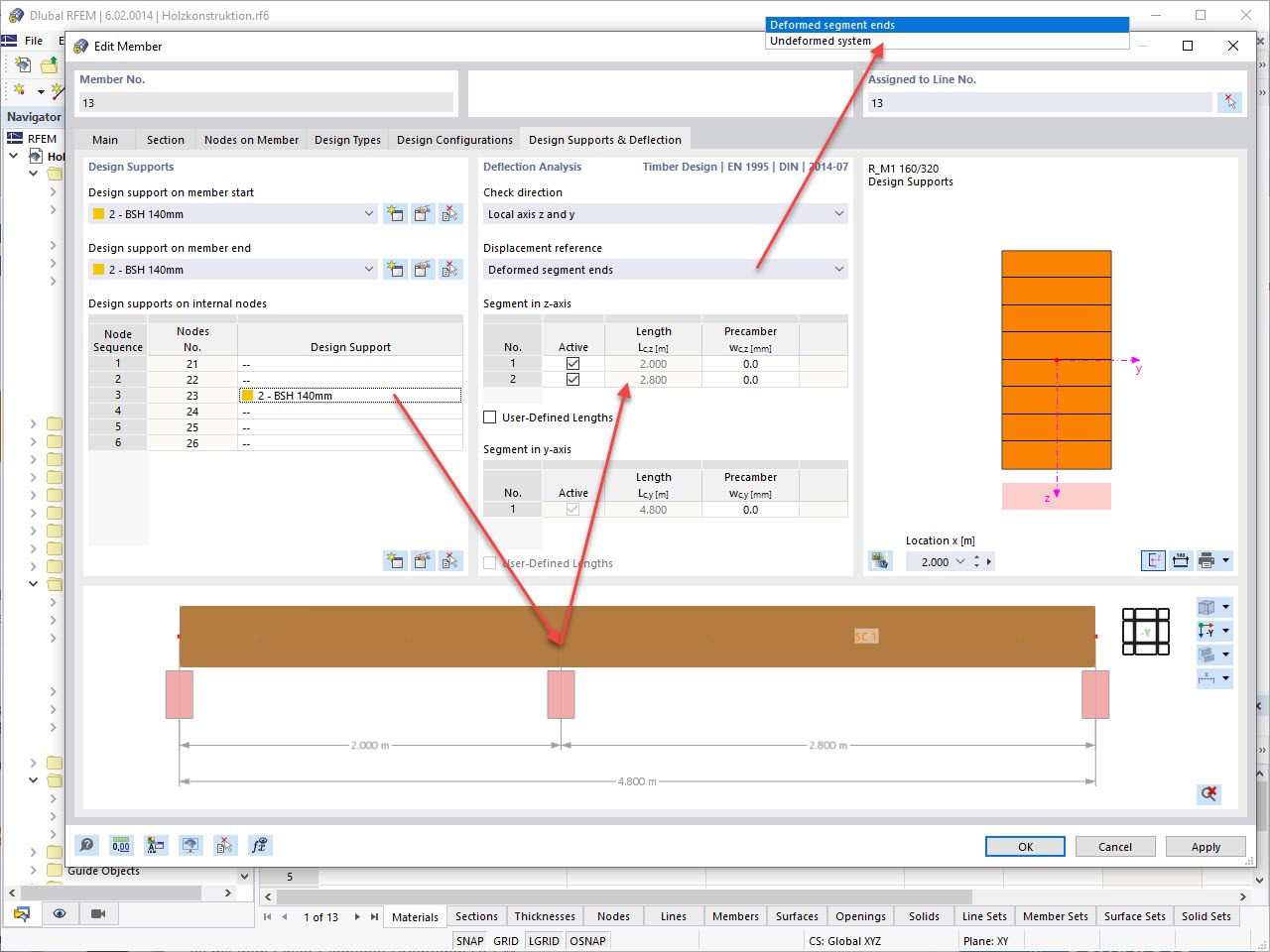
In the "Deflection and Design Support" tab under "Edit Member", the members can be clearly segmented using optimized input windows. Depending on the supports, the deformation limits for cantilever beams or single-span beams are used automatically.
By defining the design support in the corresponding direction at the member start, member end, and intermediate nodes, the program automatically recognizes the segments and segment lengths to which the allowable deformation is related. It also automatically detects whether it is a beam or a cantilever due to the defined design supports. The manual assignment, as in the previous versions (RFEM 5), is no longer necessary.
The "User-Defined Lengths" option allows you to modify the reference lengths in the table. The corresponding segment length is always used by default. If the reference length deviates from the segment length (for example, in the case of curved members), it can be adjusted.
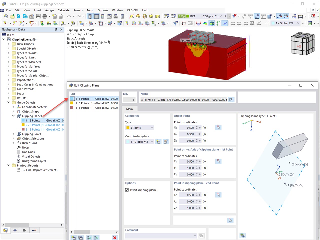
This feature also contributes to the clearly-arranged display of your results. Clipping planes are intersecting planes that you can place freely throughout the model. The zone in front of or behind the plane is consequently hidden in the display. This way, you can clearly and simply show the results in an intersection or a solid, for example.

The deformation process of the global deformation components can be represented as a movement sequence.
Which bending theory should be used for the calculation of plates and shells – Kirchhoff or Mindlin?
In my model, I obtain different results in comparison with a manual calculation and other software. What could be the reason?
What is the critical load factor and how is it possible to determine it?
I have calculated a pre-deformed structure according to the second-order analysis with RF‑STABILITY and RF‑IMP. Why are the deformations of the CO smaller than the applied pre-deformation?
How can I perform a stability/buckling analysis on a plate structure?
Why is the effective depth different with the effective depth used in shear checks?


Recommended Products for You
RFEM 6 | Main Program RFEM 6

The new generation of 3D FEA software is used for the structural analysis of members, surfaces, and solids.
Price of First License
4,790.00 USD
RFEM 6 | Design

The Concrete Design add-on allows for various design checks according to international standards. You can design members, surfaces, and columns, as well as perform punching and deformation analyses.
Price of First License
2,970.00 USD
RFEM 6 | Additional Analysis

The Construction Stages Analysis (CSA) add-on allows for considering the construction process of structures (member, surface, and solid structures) in RFEM.
Price of First License
1,760.00 USD
RFEM 6 | Additional Analysis

In RFEM, the Geotechnical Analysis add-on uses properties from soil samples to determine the soil body to be analyzed. The accurate determination of soil conditions significantly affects the quality of the structural analysis of buildings.
Price of First License
1,660.00 USD
RFEM 6 | Dynamic Analysis

The Modal Analysis add-on allows for the calculation of eigenvalues, natural frequencies, and natural periods for member, surface, and solid models.
Price of First License
1,360.00 USD
RFEM 6 | Dynamic Analysis

The Response Spectrum Analysis add-on performs seismic analysis using multi-modal response spectrum analysis. The spectra required for this can be created in compliance with the standards or can be user-defined. The equivalent static forces are generated from them. The add-on includes an extensive library of accelerograms from seismic zones that can be used to generate the response spectra.
Price of First License
1,560.00 USD
RFEM 6 | Dynamic Analysis

Using the Pushover Analysis add-on, you can analyze the seismic actions on a particular building, and thus assess whether the building can withstand an earthquake.
Price of First License
1,460.00 USD
RFEM 6 | Special Solutions

The Building Model add-on for RFEM allows you to define and manipulate a building using stories. The stories can be adjusted in many ways afterwards. The information about stories and the entire model (center of gravity) is displayed in tables and graphics.
Price of First License
1,970.00 USD
RFEM 6 | Design

With the Concrete Foundations add-on, you can design square and rectangular individual foundations. In addition to the reinforced concrete design, geotechnical verifications are also carried out. You also determine automatic reinforcement suggestions and receive detailed reinforcement plans and 3D renderings of the foundation structures.
Price of First License
1,260.00 USD
RFEM 6 | Design

The Masonry Design add-on for RFEM allows you to design masonry using the finite element method. It was developed as part of the research project titled DDMaS – Digitizing the Design of Masonry Structures. The material model represents the nonlinear behavior of the brick-mortar combination in the form of macro-modeling.
Price of First License
1,860.00 USD
RFEM 6 | Additional Analysis

The Nonlinear Material Behavior add-on allows you to consider material nonlinearities in RFEM for example, isotropic plastic, orthotropic plastic, isotropic damage).
Price of First License
1,660.00 USD
RFEM 6 | Additional Analysis

The Structure Stability add-on performs stability analysis of structures. It determines critical load factors and the corresponding stability modes.
Price of First License
1,460.00 USD
RFEM 6 | Additional Analysis

The Time-Dependent Analysis (TDA) add-on allows you to consider the time-dependent material behavior of members and surfaces. The long-term effects, such as creep, shrinkage, and aging, can influence the distribution of internal forces, depending on the structure.
Price of First License
1,160.00 USD
RFEM 6 | Additional Analysis

The Form-Finding add-on finds the optimal shape of members subjected to axial forces and tension-loaded surface models. The shape is determined by the equilibrium between the member axial force or the membrane stress and the existing boundary conditions.
Price of First License
2,320.00 USD
RFEM 6 | Special Solutions

The two-part Optimization & Costs / CO2 Emission Estimation add-on finds suitable parameters for parameterized models and blocks via the artificial intelligence (AI) technique of particle swarm optimization (PSO) for compliance with common optimization criteria. Furthermore, this add-on estimates the model costs or CO2 emissions by specifying unit costs or emissions per material definition for the structural model.
Price of First License
1,660.00 USD
RFEM 6 | Special Solutions

The Multilayer Surfaces add-on allows you to define multilayer surface structures. The calculation can be carried out with or without the shear coupling.
Price of First License
1,560.00 USD
RFEM 6 | Design

The Stress-Strain Analysis add-on performs general stress analysis by calculating the existing stresses and comparing them with the limit stresses.
Price of First License
1,360.00 USD
RFEM 6 | Design

The Steel Design add-on performs the ultimate and serviceability limit state design checks of steel members according to various standards.
Price of First License
2,970.00 USD
RFEM 6 | Design

The Timber Design add-on performs the ultimate, serviceability, and fire resistance limit state design checks of timber members according to various standards.
Price of First License
2,170.00 USD
RFEM 6 | Design

The Aluminum Design add-on performs the ultimate and serviceability limit state design checks of aluminum members according to various standards.
Price of First License
1,970.00 USD
RFEM 6 | Joints
.png?mw=600&hash=49b6a289915d28aa461360f7308b092631b1446e)
The Steel Joints add-on for RFEM allows you to analyze steel connections using an FE model. The FE model is generated automatically in the background and can be controlled via the simple and familiar input of components.
Price of First License
2,670.00 USD