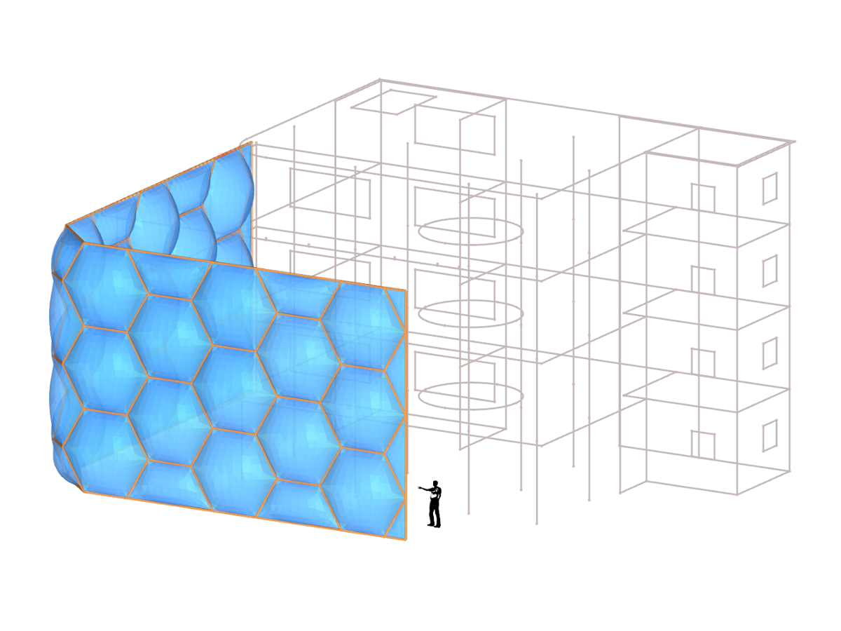
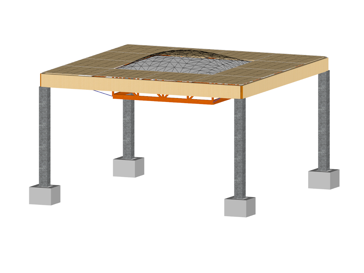
Enclosure in Form of Soccer Ball with Pneumatic Cushions
Number of Nodes | 101 |
Number of Lines | 147 |
Number of Members | 74 |
Number of Surfaces | 101 |
Number of Solids | 25 |
Number of Load Cases | 8 |
Number of Load Combinations | 7 |
Total Weight | 1.385 tons |
Dimensions (Metric) | 7.226 x 7.293 x 5.621 m |
Dimensions (Imperial) | 23.71 x 23.93 x 18.44 feet |
Program Version | 5.25.01 |
You can download this structural model to use it for training purposes or for your projects. However, we do not assume any guarantee or liability for the accuracy or completeness of the model.
![DXF Export with 3DFACE Elements](/en/webimage/009949/2421518/01-en-png-png.png?mw=512&hash=6ca63b32e8ca5da057de21c4f204d41103e6fe20)
![KB 001883 | Plate Girder Design According to AISC 360-22 in RFEM 6](/en/webimage/051561/3980997/im1.png?mw=512&hash=b8237709c4f30213fac51d86d32a42bddde72f03)
![Steel Connection Rigidity and Its Influence on Structural Design](/en/webimage/051432/3972404/Rigidity-caseA.png?mw=512&hash=3be64e68ab2956fd2b92f0afa1559b3a8c72b468)
![KB 001874 | LTB Analysis According to ADM 2020 Section F.4 in RFEM 6](/en/webimage/048099/3772420/2024-03-18_15-43-26.png?mw=512&hash=418d15db74dbdf280bc2956def625d5b0eb8704f)
![Foil Cushion with Material Model Isotropic Plastic 2D/3D](/en/webimage/006832/497212/Form-finding_de.png?mw=512&hash=78051e4822ef57bc2068122c169039849806ee35)
In RFEM, there is an option to couple surfaces with the stiffness types "Membrane" and "Membrane Orthotropic" with the material models "Isotropic Nonlinear Elastic 2D/3D" and "Isotropic Plastic 2D/3D" (add-on module RF-MAT NL erforderlich).
This functionality enables simulation of the nonlinear strain behavior of ETFE foils, for example.
![Add-on "Steel Joints for RFEM 6" | Component Library](/en/webimage/043097/3898884/steel_joints_components.png?mw=512&hash=e4f835906155863fc7019d5043b22e553dc766f9)
- Numerous component types, such as base and end plates, web angles, fin plates, gusset plates, stiffeners, tapers, or ribs for easy input of typical connection situations
- Universally applicable basic components (such as plates, welds, bolts, auxiliary planes) for modeling complex connection situations
- Graphical display of the connection geometry with dynamic updating during the input
- Wide range of cross-section shapes: I-sections, U-sections, angles, T-sections, hollow sections, built-up cross-sections and thin-walled sections
- Library in the Dlubal Center with a large number of program-side template connections, including user-defined templates
- Automatic adaptation of the connection geometry based on the relative arrangement of the components to each other – even in case of subsequent editing of the structural components
![Feature 002820 | Limit Plastic Strain for Welds](/en/webimage/050344/3881226/1.png?mw=512&hash=9d7f6c198b6d4ae6ee8f2fa8bca75f85579e14c9)
In the ultimate configuration of the steel joint design, you have the option to modify the limit plastic strain for welds.
![Component "Base Plate"](/en/webimage/050345/3936120/50345.png?mw=512&hash=3bd641cb1a2445804b338855e4debfc40c6563e9)
The "Base Plate" component allows you to design base plate connections with cast-in anchors. In this case, plates, welds, anchorages, and steel-concrete interaction are analyzed.