
Dlubal_KohlA_]_LI.jpg?mw=926&hash=f958af159dbea8cf6a70cdb18305356dd2662f16)
Steel hall with an integrated craneway and a reinforced concrete structure of an office complex
Model Used in
- Eurocode 5 | Timber Structures According to DIN EN 1995-1-1
- Eurocode 5 | Timber Structures According to DIN EN 1995-1-1
- Eurocode 5 | Timber Structures According to DIN EN 1995-1-1
- Eurocode 5 | Timber Structures According to DIN EN 1995-1-1
- Eurocode 5 | Timber Structures According to DIN EN 1995-1-1
- Steel Structures | RFEM 6 & RSTAB 9 by Dlubal Software
- Cloud Calculations in RFEM 6 and RSTAB 9
- Steel Connections | RFEM 6 by Dlubal Software
- Virtual Reality (VR) & Augmented Reality (AR) and Structural Models - Is That Possible?
Overall
This page has 0 user ratings.
| 5 star | ||
| 4 star | ||
| 3 star | ||
| 2 star | ||
| 1 star |
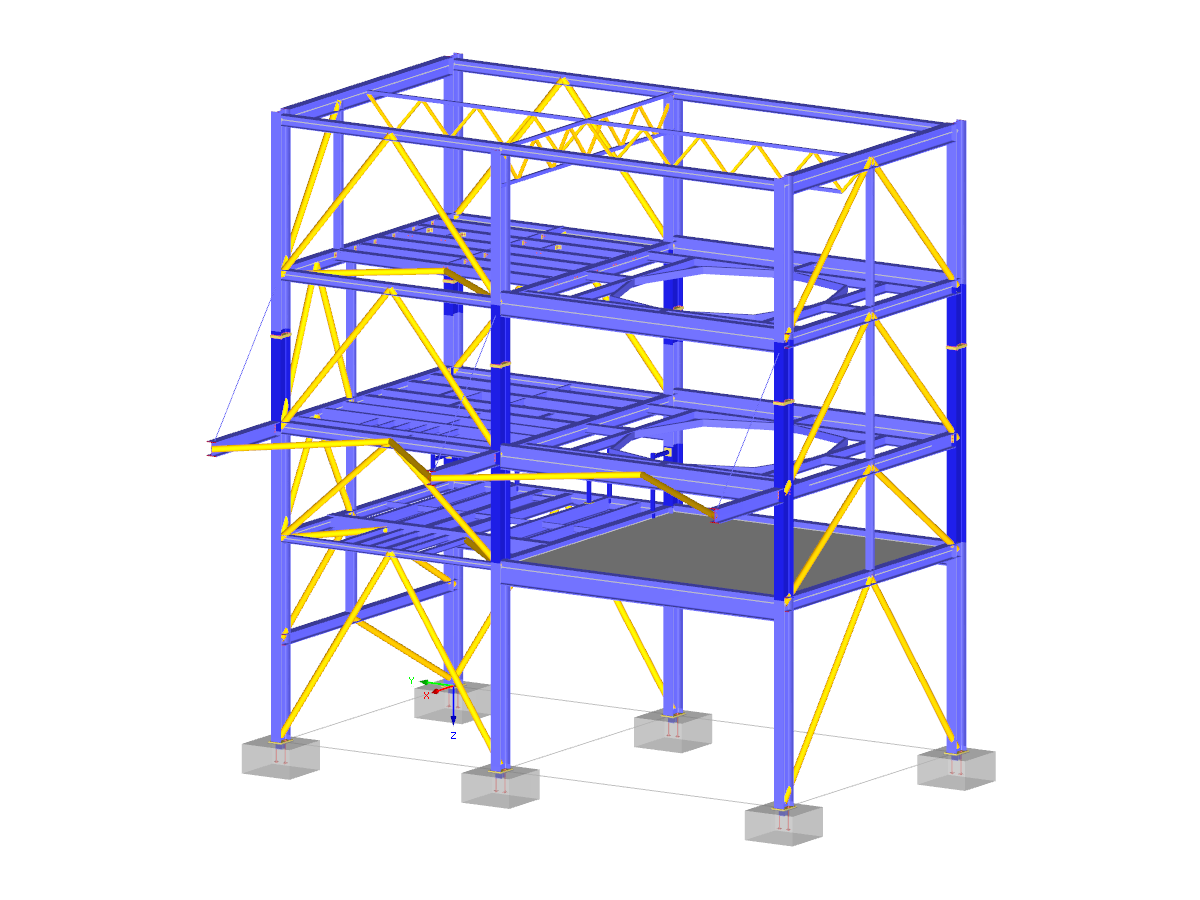
Industrial Hall with Craneway Girder
| Number of Nodes | 342 |
| Number of Lines | 543 |
| Number of Members | 455 |
| Number of Surfaces | 9 |
| Number of Load Cases | 76 |
| Number of Load Combinations | 139 |
| Number of Result Combinations | 9 |
| Total Weight | 147.000 tons |
| Dimensions (Metric) | 20.800 x 25.800 x 9.078 m |
| Dimensions (Imperial) | 68.24 x 84.65 x 29.78 feet |
| Program Version | 5.25.01 |
You can download this structural model to use it for training purposes or for your projects. However, we do not assume any guarantee or liability for the accuracy or completeness of the model.
Related Models
Duration: 00:36:44 min

Duration: 00:00:50 min

Duration: 00:00:30 min

Duration: 00:00:33 min

Duration: 00:00:21 min

Duration: 00:00:24 min

Duration: 00:00:28 min

Duration: 00:00:00 min


.png?mw=350&hash=a99dfecd6a7cd7b7c8098c3556e57edf150f9731)


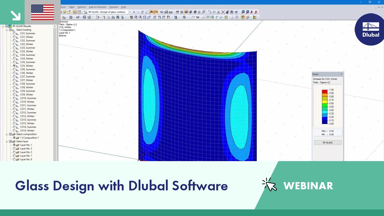
When modeling and designing glass panes in RF-GLASS, you have two different options for the FE mesh settings.

Designing vertical insulating glass requires assigning different loads on the individual layers of the entire glass unit. This occurs, for example, with simultaneous actions from wind loads and fall protection.

To work even more efficiently, RF‑GLASS allows you to create and save different, user‑defined layer structures that can be reimported later or loaded in another project.

For designing glass in the RF‑GLASS add‑on module, you can use one of two calculation methods: a 2D or a 3D calculation. The main difference between these design options is the automatic modeling of the layers in a temporary model. In a 2D calculation, each layer is generated as a surface element (plate theory); in a 3D calculation, it is generated as a solid. Depending on the selected layer composition, you can either select an option or find it preselected by the program.


The global calculation assigns the stiffness determined by means of the selected composition and the glass geometry to each surface. Then, the calculation proceeds using the plate theory. It is possible to select whether the shear coupling of layers should be considered.
In the case of the local calculation, you can further specify 2D or 3D calculation. Two-dimensional calculation means that the single-layer or laminated glass is modeled as a surface, whose thickness is calculated on the basis of the selected structure and glass geometry (using the plate theory). Similarly to the global calculation, you can optionally consider shear coupling of layers.
The 3D calculation uses solids in the model to substitute each composition layer. This way, the results are more accurate, but the calculation may take more time.
It is possible to model insulating glass only if local calculation is selected. The gas layer is always modeled as a solid element, so it is necessary to design individual insulating glass parts independently of the surrounding structure. The ideal gas law (thermal equation of state of ideal gases) is considered for the calculation and the third-order analysis.

In the add-on module, select the surfaces to be designed (for example, by using the Select function). The geometry of the glass pane, as well as the loads, is imported from the RFEM model.
Then, you have to decide if the calculation should be performed without the influence of the surrounding structure (local calculation) or with consideration of this influence (global calculation). If you select the local calculation, each surface selected for the design is detached from the model and calculated separately.
The global calculation considers the entire structure, including entered glass panes. All glass composition data and glass properties of individual layers are to be defined in RF-GLASS input windows. You can select layers of type glass, foil, and gas. The desired material can be imported directly from the library, which contains a large number of materials.
All parameters of individual layers, including their thicknesses, are editable. In addition, you can create a number of compositions in RF-GLASS, allowing you to design different types of glass together.
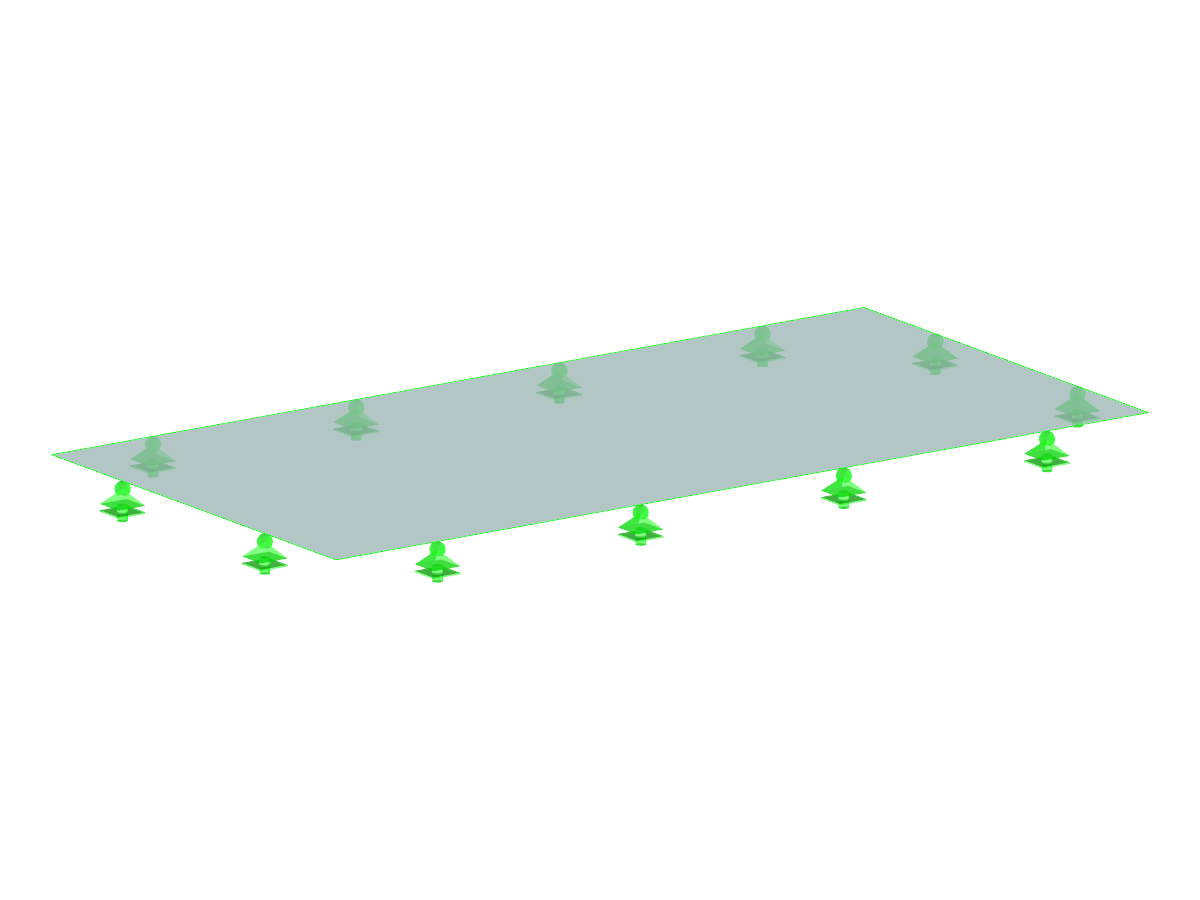
For insulating glass, you can consider external loads as well as loads due to temperature, atmospheric pressure, and altitude changes for the analysis. The module calculates these loads automatically on the basis of climatic load parameters. If you select the local calculation type, it is necessary to define line supports, nodal supports, and boundary members of the surfaces in RF-GLASS. These supports and members are considered in RF-GLASS only and have no influence on the model created in RFEM.

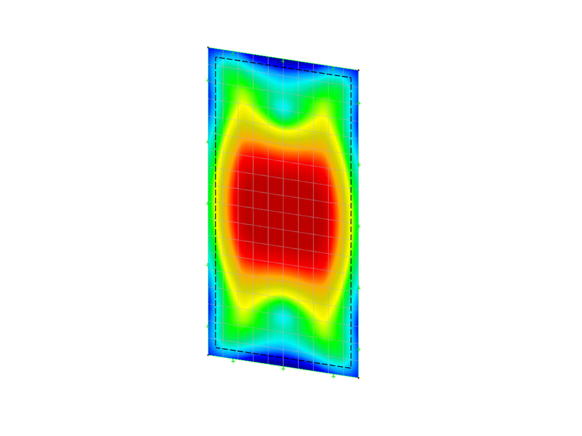
After the calculation, the results are displayed in clearly arranged result windows. Thus, you can easily find the maximum stress ratio. The stress diagram by composition is displayed as well.
Furthermore, RF-GLASS displays a parts list and, for insulating glass, the gas pressure. It is possible to display the results graphically in the RFEM model.
Both input and result tables of RF-GLASS, including graphics, can be added to the RFEM printout report. In addition, it is possible to export all tables to MS Excel.
- Design of single-layer or laminated glass as well as gas layer insulating glass
- design of curved glass
- Option to select either local calculation without regard to the influence of a surrounding structure, or global calculation with regard to the influence of an entire structure
- Calculation of limit stresses according to DIN 18008:2010-12 or TRLV:2006-08
- Assignment of loads to load duration classes
- Extensive material library including all common glass, foil, and gas types in compliance with the DIN 18008:2010-12, E DIN EN 13474 standards, and the TRLV:2006-08 regulation
- Optional consideration of shear coupling of layers
- Consideration of climatic loads
- Calculation according to the linear static analysis or nonlinear analysis according to the large deformation analysis. analysis
- Stress analysis, ultimate limit state design, serviceability limit state design
- Graphical representation of all results in RFEM
- Possibility to filter results and color scales in result tables
- Direct data export to MS Excel
Is it possible to design a spherically curved glass pane in RF‑GLASS?
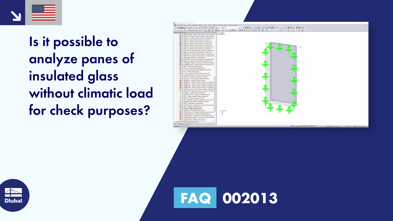
Is it possible to analyze panes of insulated glass without climatic load for check purposes?
Which stresses are most important for glass design consideration when using RF-GLASS?
Where can I find the details of a layer composition in the RF‑GLASS add-on module?
I would like to design a glass pane with temperature loads. In this case, a message appears saying that the load case includes "temperature" surface load types that are not transferred to the created temporary model. How can I consider temperature loads?
Are there any programs or add-on modules specially developed for glass structures?
-querkraft-hertha-hurnaus.jpg?mw=350&hash=3306957537863c7a7dc17160e2ced5806b35a7fb)


Recommended Products for You
RFEM 5 | Main Program RFEM

Structural engineering software for a finite element analysis (FEA) of planar and spatial structural systems consisting of plates, walls, shells, members (beams), solids, and contact elements
Price of First License
4,690.00 USD
RFEM 6 | Main Program RFEM 6

The new generation of 3D FEA software is used for the structural analysis of members, surfaces, and solids.
Price of First License
4,790.00 USD
RFEM 5 | Glass Structures

Design of single-layer, laminated, and insulating glass
Price of First License
1,660.00 USD