
When modeling and designing glass panes in RF-GLASS, you have two different options for the FE mesh settings.
When modeling and designing glass panes in RF-GLASS, you have two different options for the FE mesh settings.


In the wind simulation, it is possible to consider member coatings (for example, from ice loads).

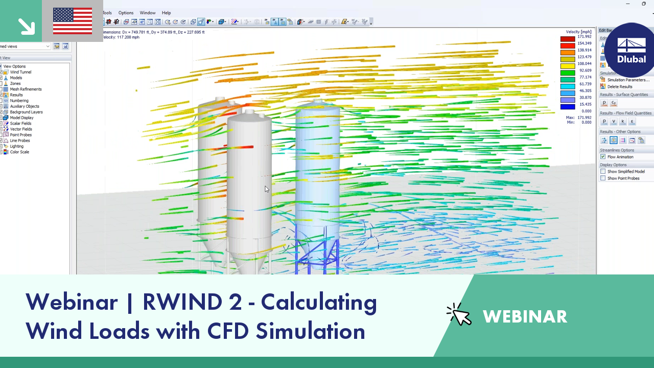
In RFEM and RSTAB, you can visualize the flow field quantities of pressure, velocity, turbulence kinetic energy, and turbulence dissipation rate for the wind simulation.
The clipping planes are aligned with the respective wind direction.
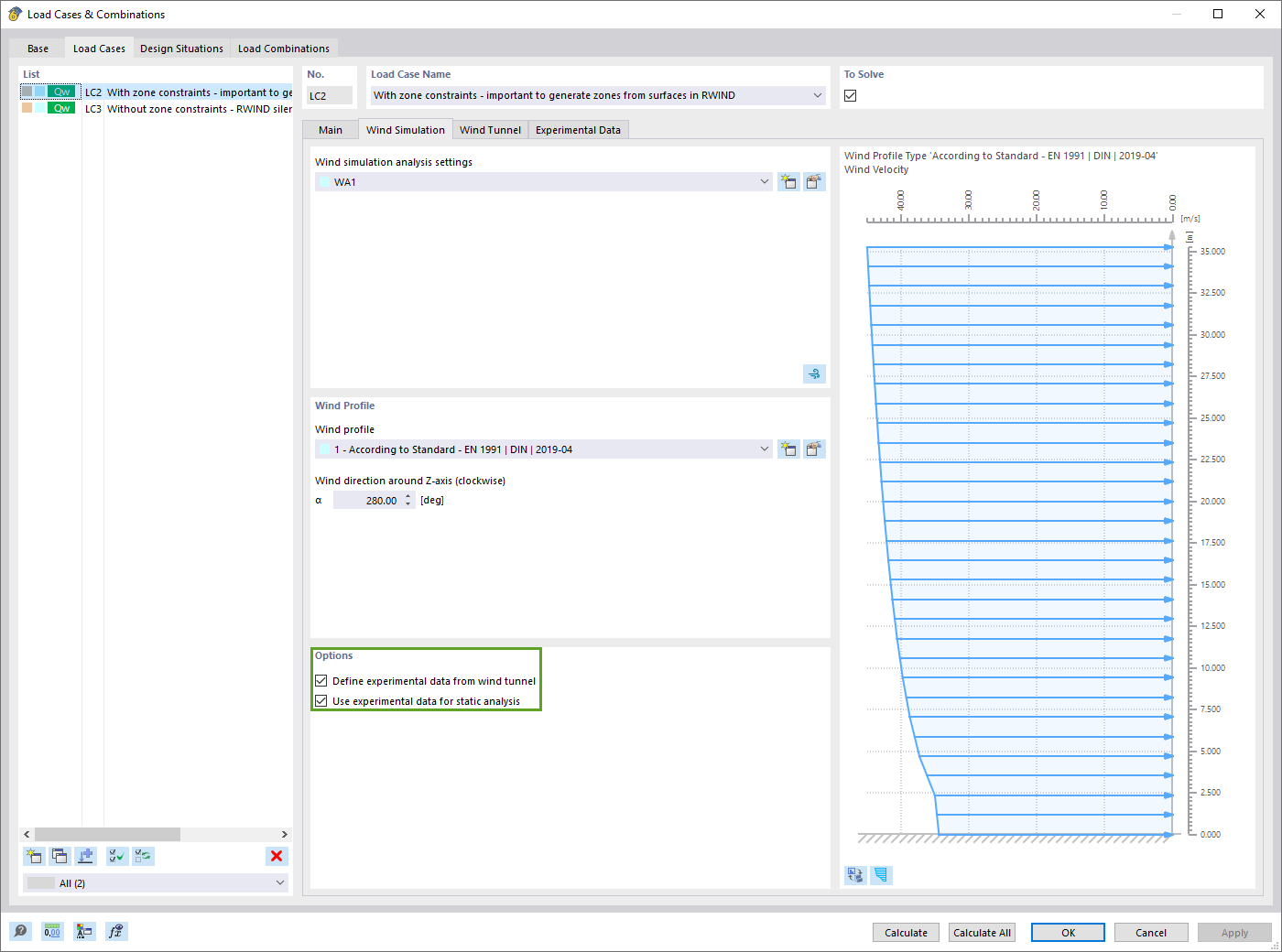
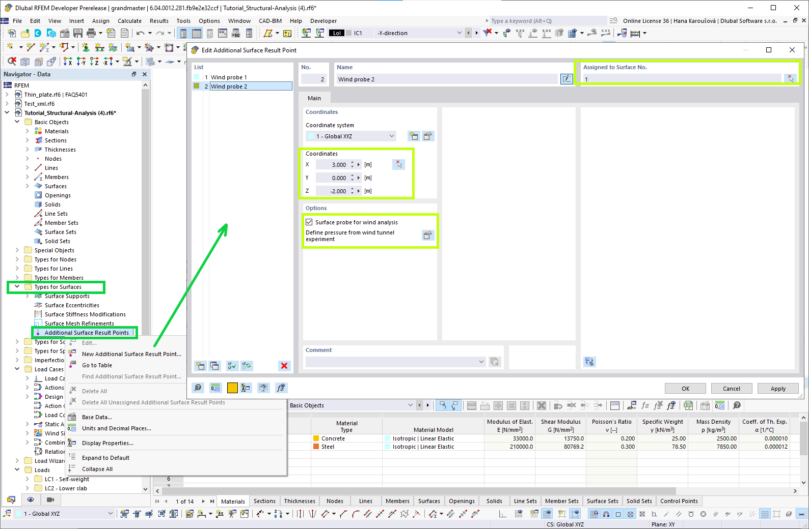
If you have experimentally determined surface pressures available for a model, you can apply them to a structural model in RFEM 6, process them in RWIND 2, and use them as wind loads in the structural analysis of RFEM 6.
You can find out how to apply the experimentally determined values in this Knowledge Base article: Static Analysis with Wind Loads from Experimentally Measured Pressures Using RWIND 2 and RFEM 6
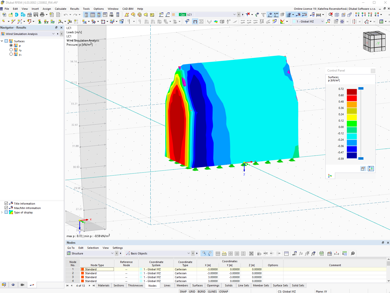
You can display the RWIND results directly in the main program. In the Navigator - Results, select the Wind Simulation Analysis result type from the list above.
Currently, the following results are available, which refer to the RWIND computational mesh:
How can I find RWIND results such as forces data in ParaView?
How can I obtain wind force coefficient in RWIND?
How can I determine the sufficient total simulation time for an accurate transient wind analysis in RWIND?
How can I determine the appropriate total simulation time for a transient analysis in RWIND?

The new generation of 3D FEA software is used for the structural analysis of members, surfaces, and solids.

The Form-Finding add-on finds the optimal shape of members subjected to axial forces and tension-loaded surface models. The shape is determined by the equilibrium between the member axial force or the membrane stress and the existing boundary conditions.


-querkraft-hertha-hurnaus.jpg?mw=350&hash=3306957537863c7a7dc17160e2ced5806b35a7fb)