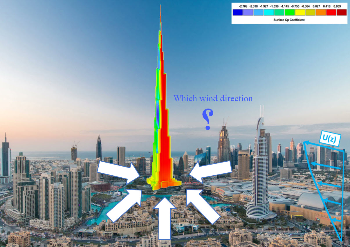
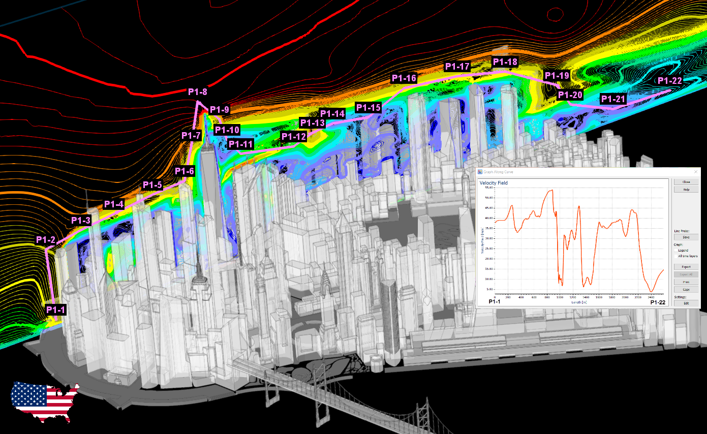
The importance of wind-structure interaction has risen in recent years due to an increasing number of structures of varying heights and shapes. Experimental and numerical approaches are used to determine the interaction. Many structures are being evaluated in wind tunnels as part of the experimental investigations. In this approach, the impacts caused by wind loads may be calculated. Large-scale structures, such as tall buildings, bridges, and stadiums, benefit greatly from wind tunnel testing, but they are very expensive and time-consuming methods. Structural wind loads are also determined using CFD and experimental investigations, which are cheaper and faster methods.
KB 001852 | How to Comply With the Requirements of the Eurocode Using the Application of CFD in Wind Load Calculation


In RFEM 6, there is a hierarchical control between load transfer surfaces and floors in the building model. This means that you can also create walls from load transfer surfaces to take into account curtain walls, for example.

When generating shear walls and deep beams, you can assign not only surfaces and cells, but also members.
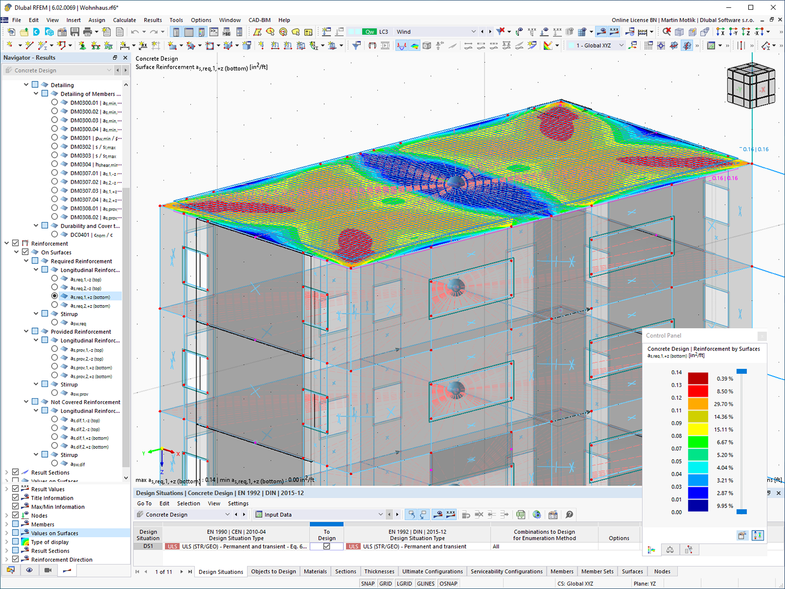
The building model is calculated in two phases:
- Global 3D calculation of the global model, where the slabs are modeled as a rigid plane (diaphragm) or as a bending plate
- Local 2D calculation of the individual floors
After the calculation, the results of the columns and walls from the 3D calculation and the results of the slabs from the 2D calculation are combined in a single model. This means that there is no need to switch between the 3D model and the individual 2D models of the slabs. The user only works with one model, saves valuable time, and avoids possible errors in the manual data exchange between the 3D model and the individual 2D ceiling models.
The vertical surfaces in the model can be divided into shear walls and opening lintels. The program automatically generates internal result members from these wall objects, so they can be designed as members according to any standard in the Concrete Design add-on.

Several modeling tools are available for elements in building models:
- Vertical line
- Column
- Wall
- Beam
- Rectangular floor
- Polygonal floor
- Rectangular floor opening
- Polygonal floor opening
This feature allows you to define the element on the ground plane (for example, with a background layer) with the associated multiple element creation in space.
How can I determine the sufficient total simulation time for an accurate transient wind analysis in RWIND?
What is the component-based Finite Element Method (CBFEM)?
How can we introduce experimental wind tunnel data in RFEM?


-querkraft-hertha-hurnaus.jpg?mw=350&hash=3306957537863c7a7dc17160e2ced5806b35a7fb)


