How may I help you?
Do you have any questions about Dlubal products or need assistance in selecting the right one for your project?
I'm here to help. You can easily reach me through the contact options provided below.
Looking forward to hearing from you!
Amy Heilig, PE
CEO – USA Subsidiary | Sales Engineer


Design Single-Layer, Laminated, and Insulated Glass
Total items: 4

.png?mw=1024&hash=42879212be74180af1492f8d9df8267ff6298e84)


RF-GLASS | Features
- Design of single-layer or laminated glass as well as gas layer insulating glass
- design of curved glass
- Option to select either local calculation without regard to the influence of a surrounding structure, or global calculation with regard to the influence of an entire structure
- Calculation of limit stresses according to DIN 18008:2010-12 or TRLV:2006-08
- Assignment of loads to load duration classes
- Extensive material library including all common glass, foil, and gas types in compliance with the DIN 18008:2010-12, E DIN EN 13474 standards, and the TRLV:2006-08 regulation
- Optional consideration of shear coupling of layers
- Consideration of climatic loads
- Calculation according to the linear static analysis or nonlinear analysis according to the large deformation analysis. analysis
- Stress analysis, ultimate limit state design, serviceability limit state design
- Graphical representation of all results in RFEM
- Possibility to filter results and color scales in result tables
- Direct data export to MS Excel

RF-GLASS | Input
In the add-on module, select the surfaces to be designed (for example, by using the Select function). The geometry of the glass pane, as well as the loads, is imported from the RFEM model.
Then, you have to decide if the calculation should be performed without the influence of the surrounding structure (local calculation) or with consideration of this influence (global calculation). If you select the local calculation, each surface selected for the design is detached from the model and calculated separately.
The global calculation considers the entire structure, including entered glass panes. All glass composition data and glass properties of individual layers are to be defined in RF-GLASS input windows. You can select layers of type glass, foil, and gas. The desired material can be imported directly from the library, which contains a large number of materials.
All parameters of individual layers, including their thicknesses, are editable. In addition, you can create a number of compositions in RF-GLASS, allowing you to design different types of glass together.
For insulating glass, you can consider external loads as well as loads due to temperature, atmospheric pressure, and altitude changes for the analysis. The module calculates these loads automatically on the basis of climatic load parameters. If you select the local calculation type, it is necessary to define line supports, nodal supports, and boundary members of the surfaces in RF-GLASS. These supports and members are considered in RF-GLASS only and have no influence on the model created in RFEM.

RF-GLASS | Calculation
The global calculation assigns the stiffness determined by means of the selected composition and the glass geometry to each surface. Then, the calculation proceeds using the plate theory. It is possible to select whether the shear coupling of layers should be considered.
In the case of the local calculation, you can further specify 2D or 3D calculation. Two-dimensional calculation means that the single-layer or laminated glass is modeled as a surface, whose thickness is calculated on the basis of the selected structure and glass geometry (using the plate theory). Similarly to the global calculation, you can optionally consider shear coupling of layers.
The 3D calculation uses solids in the model to substitute each composition layer. This way, the results are more accurate, but the calculation may take more time.
It is possible to model insulating glass only if local calculation is selected. The gas layer is always modeled as a solid element, so it is necessary to design individual insulating glass parts independently of the surrounding structure. The ideal gas law (thermal equation of state of ideal gases) is considered for the calculation and the third-order analysis.

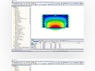
RF-GLASS | Results
After the calculation, the results are displayed in clearly arranged result windows. Thus, you can easily find the maximum stress ratio. The stress diagram by composition is displayed as well.
Furthermore, RF-GLASS displays a parts list and, for insulating glass, the gas pressure. It is possible to display the results graphically in the RFEM model.
Both input and result tables of RF-GLASS, including graphics, can be added to the RFEM printout report. In addition, it is possible to export all tables to MS Excel.

.png?mw=192&hash=f63e4a3f1836233005de32f60201d5392e507cf1)
Calculate Your Price

Total Amount 1,660.00 USD
The price is valid for United States.


