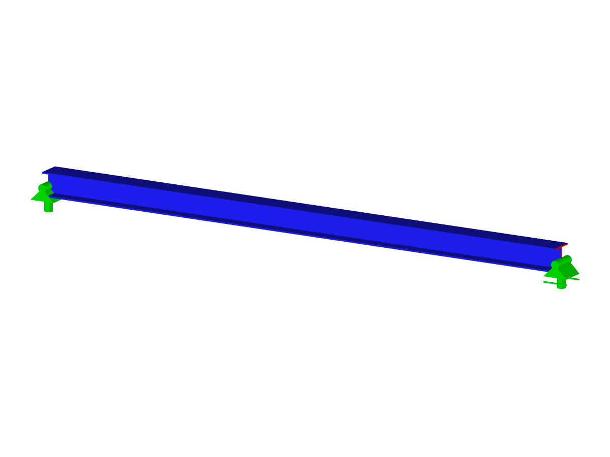
The model shows how to determine the correct load application point for positive lateral loads according to RF-/STEEL EC3 and RF-/STEEL AISC. It takes into account precise signs and eccentricity when determining the load application, load application point, and load application position. In addition, the influence of the lateral-torsional buckling moment is professionally illustrated. The accompanying image provides clear visual notes on the geometric display of the steel beam. All aspects are presented in a comprehensible way using technical calculation methods.
| 5 star | ||
| 4 star | ||
| 3 star | ||
| 2 star | ||
| 1 star |
Load Application Point – Steel Beam Analysis
| Number of Nodes | 2 |
| Number of Lines | 1 |
| Number of Members | 1 |
| Number of Load Cases | 1 |
| Total Weight | 0,422 t |
| Dimensions (Metric) | 10.960 x 0.960 x 0.960 m |
| Dimensions (Imperial) | 35.96 x 3.15 x 3.15 feet |
| Program Version | 5.23.02 |
You can download this structural model to use it for training purposes or for your projects. However, we do not assume any guarantee or liability for the accuracy or completeness of the model.
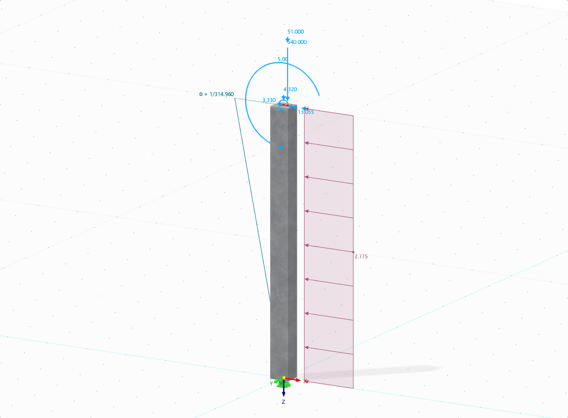
The aim of this technical article is to perform a design according to the general design method of Eurocode 2, using the example of a slender reinforced concrete column.

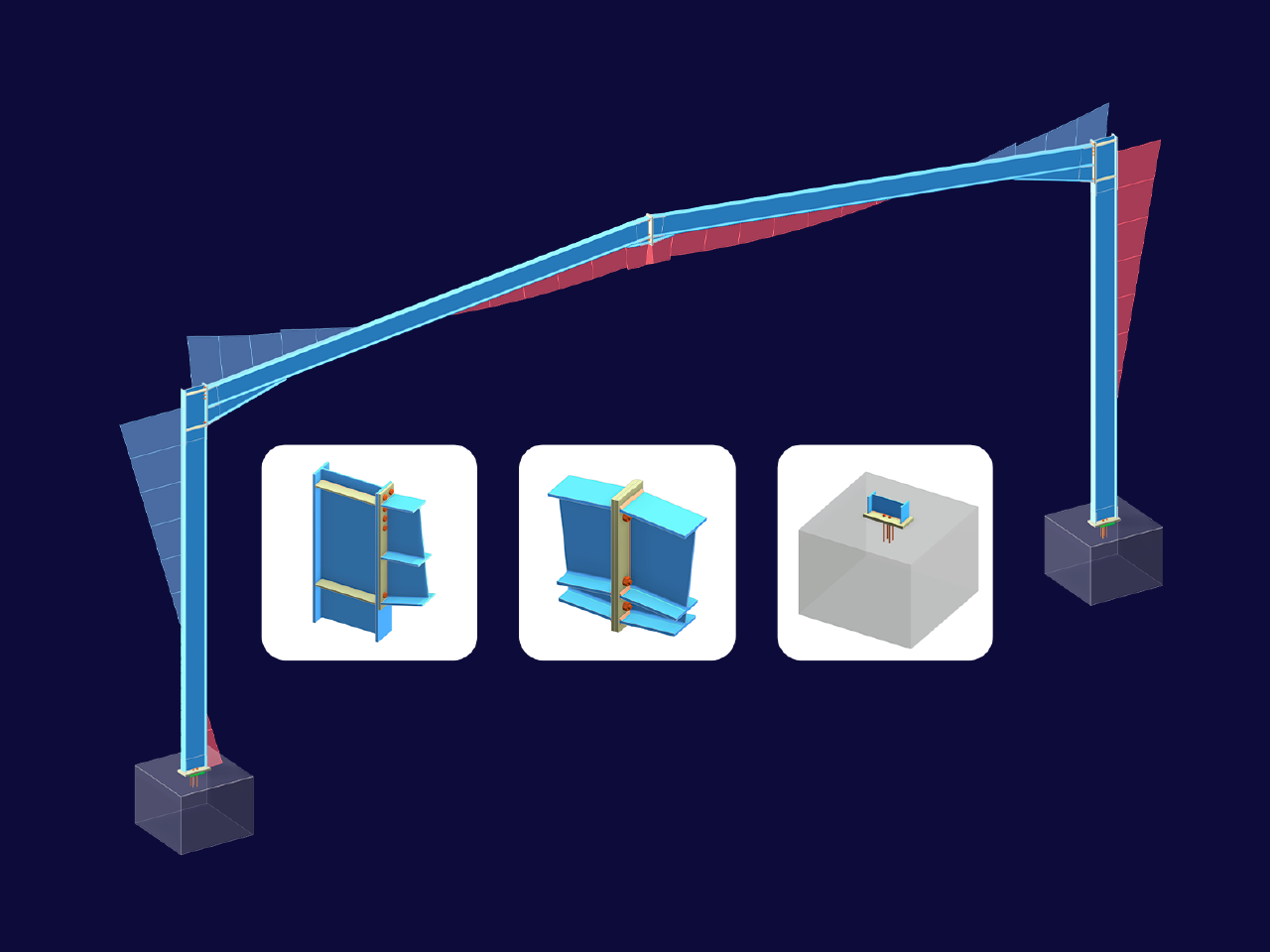

In RFEM 6, there is a hierarchical control between load transfer surfaces and floors in the building model. This means that you can also create walls from load transfer surfaces to take into account curtain walls, for example.
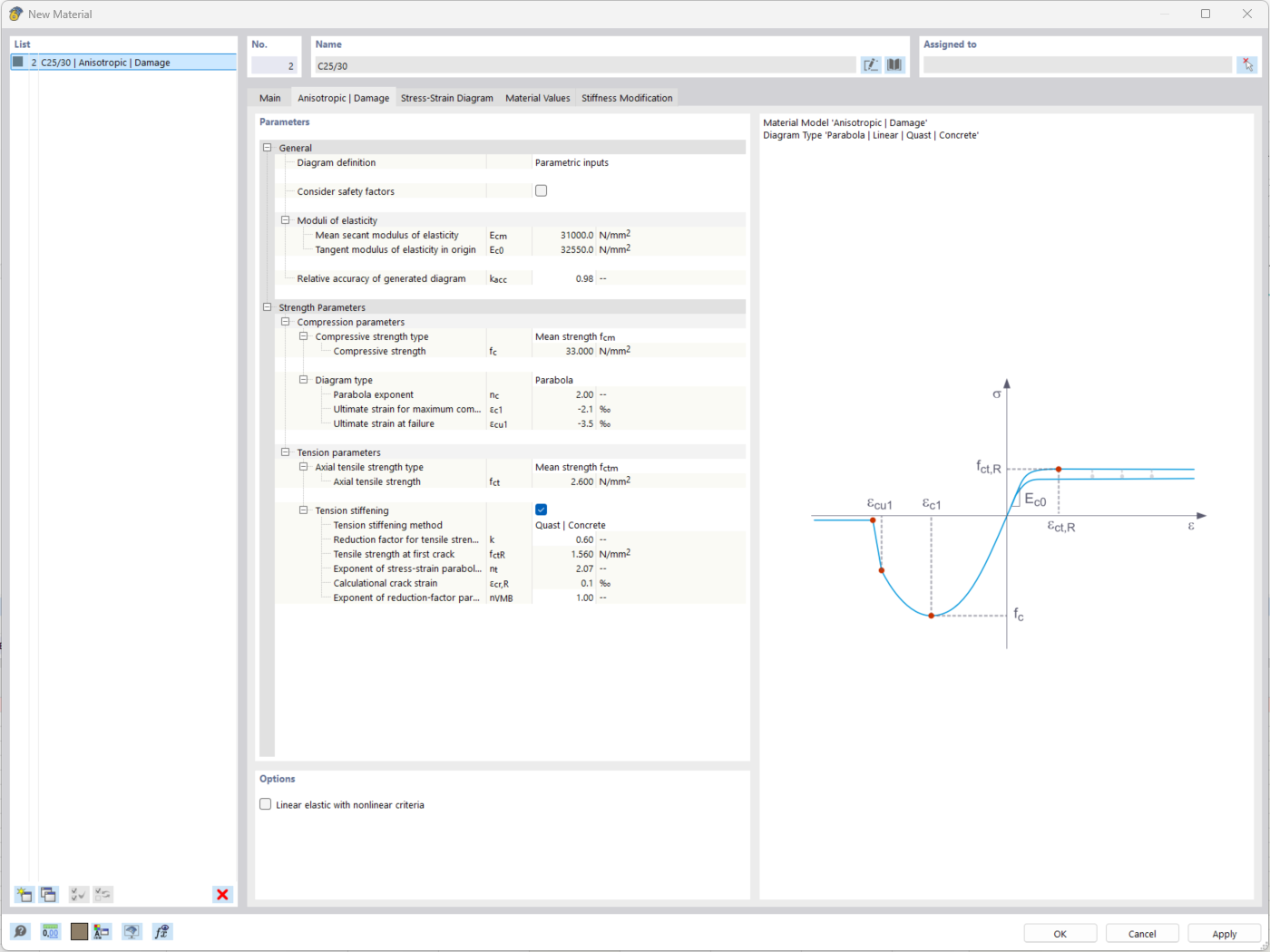
The "Nonlinear Material Behavior" add-on includes the Anistropic | Damage material model for concrete structural components. This material model allows you to consider concrete damage for members, surfaces, and solids.
You can define an individual stress-strain diagram via a table, use the parametric input to generate the stress-strain diagram, or use the predefined parameters from the standards. Furthermore, it is possible to consider the tension stiffening effect.
For the reinforcement, both nonlinear material models "Isotropic | Plastic (Members)" and "Isotropic | Nonlinear Elastic (Members)" are available.
It is possible to consider the long-term effects due to creep and shrinkage using the "Static Analysis | Creep & Shrinkage (Linear)" analysis type that has been recently released. Creep is taken into account by stretching the stress-strain diagram of the concrete using the factor (1+phi), and shrinkage is taken into account as the pre-strain of the concrete. More detailed time step analyses are possible using the "Time-Dependent Analysis (TDA)" add-on.
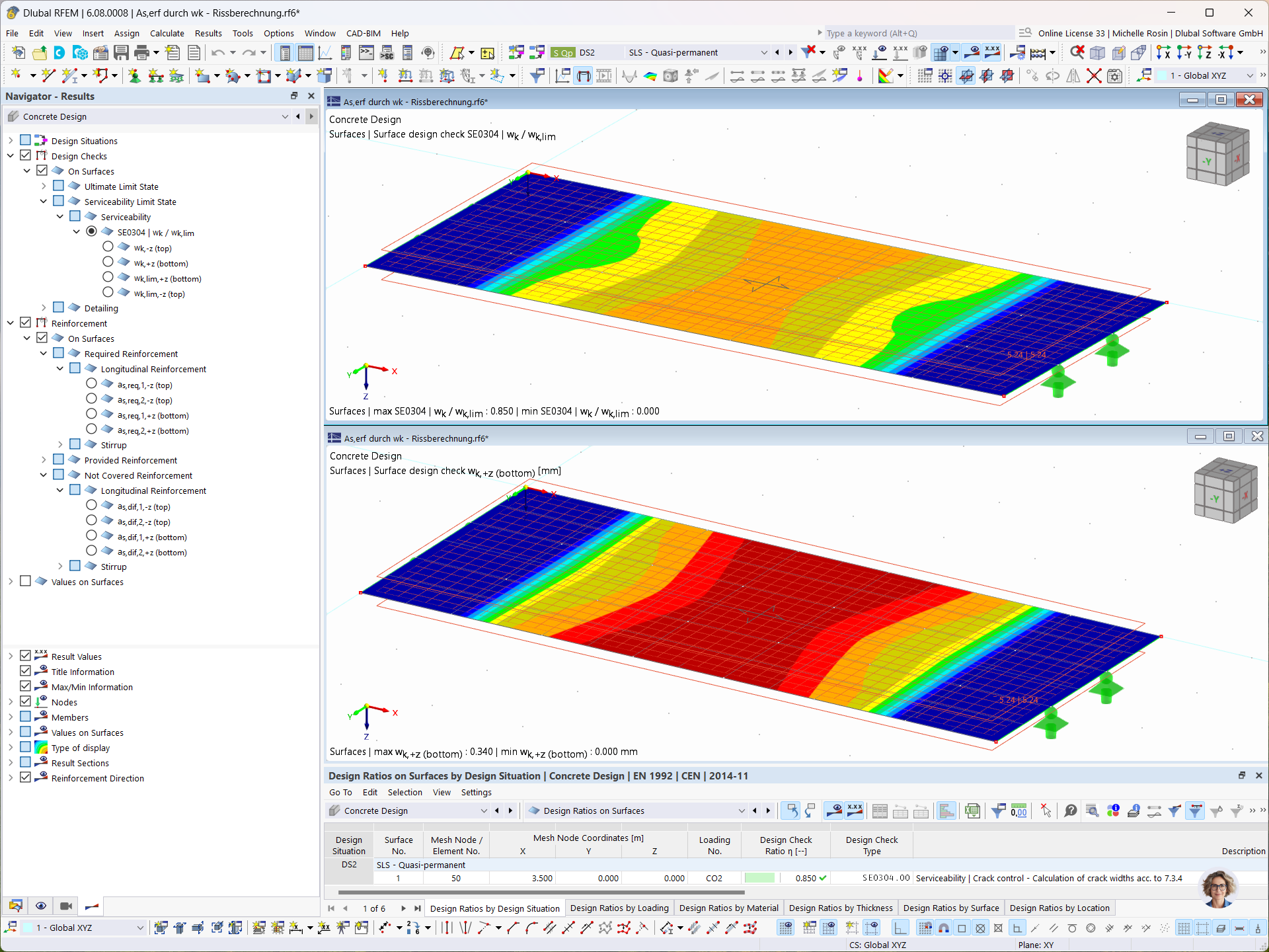
In the Concrete Design add-on, you can determine the required longitudinal reinforcement for the direct crack width analysis (w k).

For the design of reinforced concrete members, there is the option to automatically determine the number or diameter of rebars.
Why is the effective depth different with the effective depth used in shear checks?
In the Steel Joints add-on, I get high utilization ratios for preloaded bolts in the tension design. Where do these high utilization ratios come from and how can I evaluate the load-bearing reserves of the bolt?
How can I check the determination of the required reinforcement?
How can treating a connection as fully rigid result in an uneconomical design?
Is it possible to consider shear panels and rotational restraints in the global calculation?
How can I determine the sufficient total simulation time for an accurate transient wind analysis in RWIND?



.png?mw=350&hash=c6c25b135ffd26af9cd48d77813d2ba5853f936c)


_1.jpg?mw=350&hash=ab2086621f4e50c8c8fb8f3c211a22bc246e0552)







.png?mw=600&hash=49b6a289915d28aa461360f7308b092631b1446e)


