

The model presents how the final results of the design of members and sets of members in the RF-/STEEL EC3 add-on module are displayed graphically in the work windows of RFEM and RSTAB. Use the load case menu to select the corresponding design case and visualize the results in detail.
Model Used in
Overall
This page has 0 user ratings.
| 5 star | ||
| 4 star | ||
| 3 star | ||
| 2 star | ||
| 1 star |
Visualization of Design Results
| Number of Nodes | 2 |
| Number of Members | 1 |
| Number of Load Cases | 2 |
| Number of Load Combinations | 8 |
| Number of Result Combinations | 3 |
| Total Weight | 1,414 t |
| Dimensions (Metric) | 8.034 x 0.534 x 0.534 m |
| Dimensions (Imperial) | 26.36 x 1.75 x 1.75 feet |
| Program Version | 8.25.00 |
You can download this structural model to use it for training purposes or for your projects. However, we do not assume any guarantee or liability for the accuracy or completeness of the model.


Duration: 00:01:00 min

Duration: 00:00:12 min

Duration: 00:44:46 min

Duration: 00:00:23 min

Duration: 00:00:29 min

Duration: 01:03:34 min

Duration: 01:15:35 min

Duration: 00:00:51 min


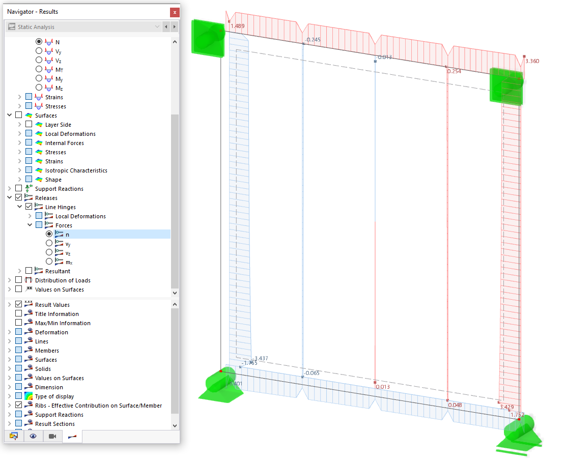
In this article, the design of a timber panel wall with the beam panel thickness type is performed.
.png?mw=512&hash=4a84cbc5b1eacf1afb4217e8e43c5cb50ed8d827)
This article provides a comprehensive overview of essential seismic analysis methods, explaining their principles and applications, as well as the scenarios in which they are most effective

Fire design according to Chapter 16 of the NDS [1] for wood members and surfaces is available in the Timber Design add-on. This article shows how the charring of wood and reduced cross-sectional dimensions can be accounted for in the fire design with an example from AWC Technical Report No. 10 [2].

When calculating regular structures, data input is often not complicated, but it is time-consuming. Save your valuable time with input automation. The task described in the present article is to consider the stories of a house as single construction stages. Data are entered using a C# program so that the user does not have to enter the elements of the individual floors manually.


.png?mw=350&hash=22d4cc5696e7961e8d9ee2a7db1c2f74839b0477)


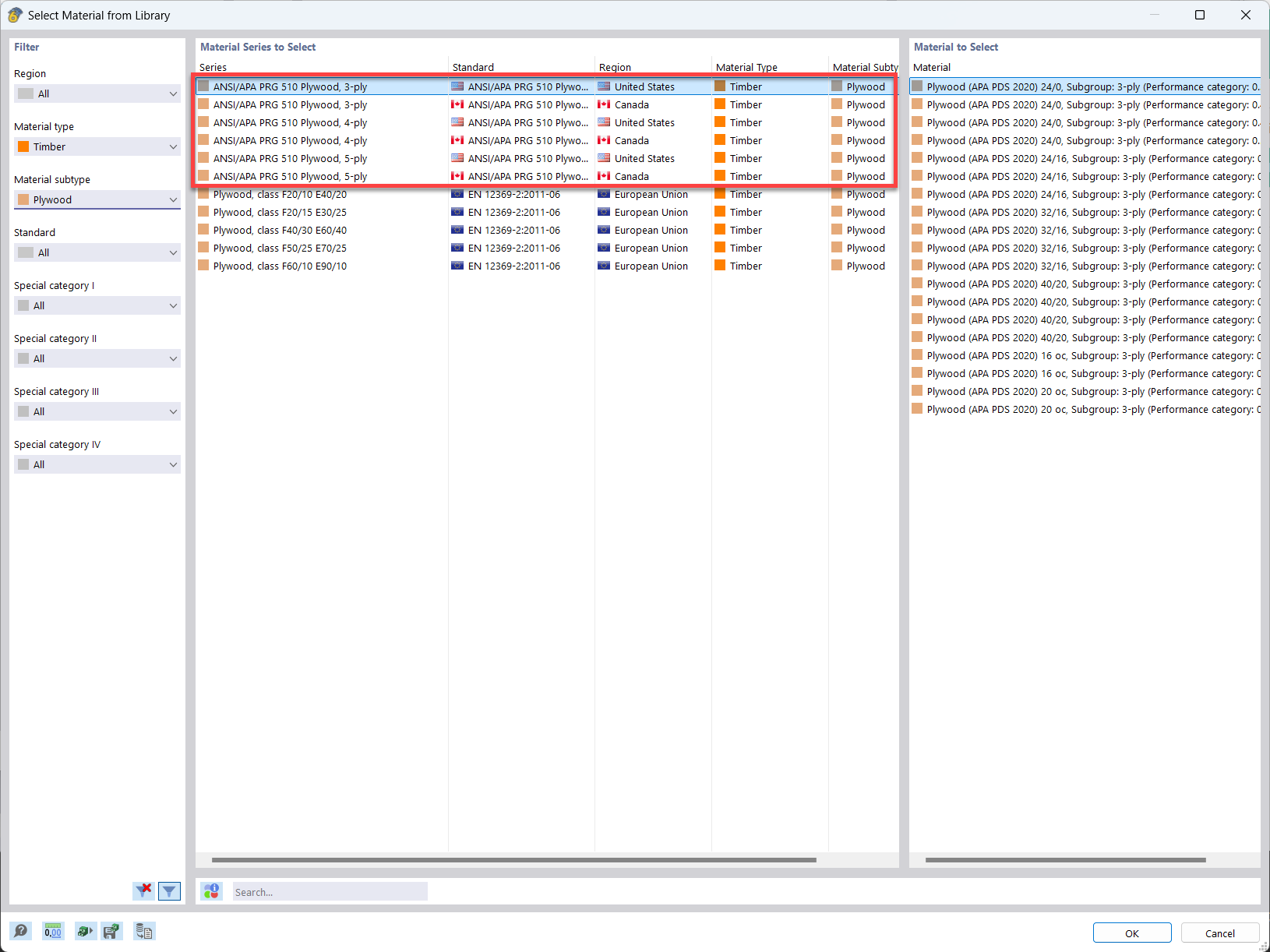
In the material library of RFEM, you can find plywood materials according to the US and Canadian standards ANSI/APA PRG 510 Plywood (USA/CAN).
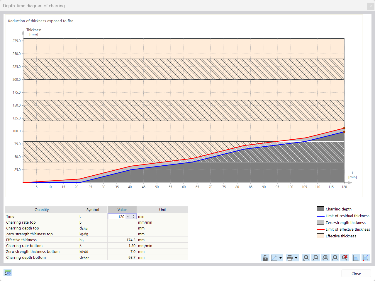
For the fire resistance design of timber surfaces, you can display a charring diagram depending on the time of fire exposure.
It is also possible to print this charring diagram into the printout report.
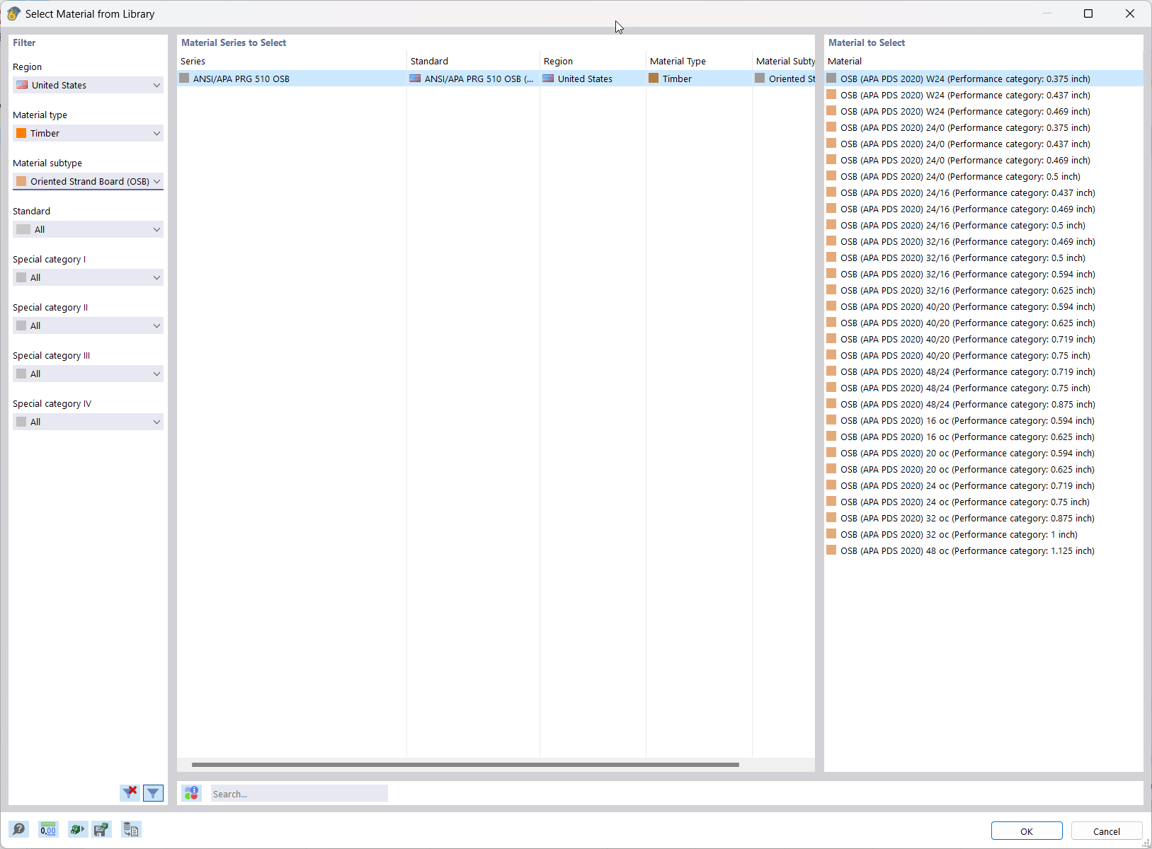
In RFEM, the oriented strand board (OSB) material is available for the USA and Canada. The material parameters are taken from the "Panel Design Specification manual".

Using the "Beam Panel" thickness type, you can model timber panel elements in 3D space. Simply specify the surface geometry and the timber panel elements are automatically generated using an internal member-surface construct, including the element connection stiffness. The Beam Panel thickness type is defined using the Multilayer Surfaces add-on.
A "beam panel" provides you with the following advantages:
- Single-sided or double-sided sheathing
- Automatic calculation of a semi-rigid coupling between studs and sheathing
- Nailed sheathing connection
- Stapled sheathing connection
- User-defined sheathing connection
- Representation as a complete geometric 3D object (frame, studs, surface, etc.), including eccentricity and automatically calculated stiffness between elements
- Consider openings via surface cells
- Design of the individual structural elements utilizing the Timber Design add-on (full shear wall design planned for a future release)
- Other material options available (e.g., particle board, gypsum, or fiberboard sheathing with cold-formed steel sections)
I have a question about the results of the serviceability limit state design: How is the increment of the dead load by the factor of 1.8 and the imposed load by 1.48 explained in the result combinations for the SLS design?
How can I change the language in the RX‑TIMBER add-on module?
Do I need to add a line hinge/line release for the CLT wall-to-floor connection in the Building Model add-on?
How can I add counteracting dead loads (0.9*D) in NBC load combinations?
How can I perform member design by case for different settings in the design configuration?
How can I exclude the dead load in NBC load combinations when performing a deflection check?


Recommended Products for You
RFEM 6 | Main Program RFEM 6

The new generation of 3D FEA software is used for the structural analysis of members, surfaces, and solids.
Price of First License
4,790.00 USD
RFEM 6 | Design

The Timber Design add-on performs the ultimate, serviceability, and fire resistance limit state design checks of timber members according to various standards.
Price of First License
2,170.00 USD
RFEM 6 | Additional Analysis

The Structure Stability add-on performs stability analysis of structures. It determines critical load factors and the corresponding stability modes.
Price of First License
1,460.00 USD
RSTAB 9 | Main Program RSTAB 9

The modern 3D structural analysis and design program is suitable for the structural and dynamic analysis of beam structures as well as the design of concrete, steel, timber, and other materials.
Price of First License
3,380.00 USD
RSTAB 9 | Design
The Timber Design add-on performs the ultimate, serviceability, and fire resistance limit state design checks of timber members according to various standards.
Price of First License
2,170.00 USD
RX-TIMBER 2 | Timber Structures

Timber design of single-span and wide-span glulam beams according to Eurocode 5 or DIN 1052
Price of First License
1,260.00 USD
RX-TIMBER 2 | Timber Structures

Timber design of simple, continuous, and Gerber beams with or without cantilever according to Eurocode 5 or DIN 1052
Price of First License
400.00 USD
RX-TIMBER 2 | Timber Structures

Timber design of rectangular and circular columns according to Eurocode 5 or DIN 1052
Price of First License
400.00 USD
RX-TIMBER 2 | Timber Structures

Timber design of coupled purlins and continuous beams according to Eurocode 5 or DIN 1052
Price of First License
400.00 USD
RX-TIMBER 2 | Timber Structures

Timber design of three-hinged frames with finger joint connections according to Eurocode 5 or DIN 1052
Price of First License
400.00 USD
RX-TIMBER 2 | Timber Structures

Timber design of stiffening truss bracing according to Eurocode 5 or DIN 1052
Price of First License
400.00 USD
RX-TIMBER 2 | Timber Structures

Timber design of flat, monopitch, and duopitch roofs according to Eurocode 5
Price of First License
400.00 USD
RFEM 6 | Additional Analysis

The Construction Stages Analysis (CSA) add-on allows for considering the construction process of structures (member, surface, and solid structures) in RFEM.
Price of First License
1,760.00 USD
RFEM 6 | Additional Analysis

The Torsional Warping (7 DOF) add-on allows you to consider cross-section warping as an additional degree of freedom.
Price of First License
1,660.00 USD
RFEM 6 | Design

The Stress-Strain Analysis add-on performs general stress analysis by calculating the existing stresses and comparing them with the limit stresses.
Price of First License
1,360.00 USD
RFEM 6 | Design

The Concrete Design add-on allows for various design checks according to international standards. You can design members, surfaces, and columns, as well as perform punching and deformation analyses.
Price of First License
2,970.00 USD
RFEM 6 | Design

The Steel Design add-on performs the ultimate and serviceability limit state design checks of steel members according to various standards.
Price of First License
2,970.00 USD
RFEM 6 | Design

The Masonry Design add-on for RFEM allows you to design masonry using the finite element method. It was developed as part of the research project titled DDMaS – Digitizing the Design of Masonry Structures. The material model represents the nonlinear behavior of the brick-mortar combination in the form of macro-modeling.
Price of First License
1,860.00 USD
RFEM 6 | Design

The Aluminum Design add-on performs the ultimate and serviceability limit state design checks of aluminum members according to various standards.
Price of First License
1,970.00 USD
RFEM 6 | Joints
.png?mw=600&hash=49b6a289915d28aa461360f7308b092631b1446e)
The Steel Joints add-on for RFEM allows you to analyze steel connections using an FE model. The FE model is generated automatically in the background and can be controlled via the simple and familiar input of components.
Price of First License
2,670.00 USD
RSTAB 9 | Additional Analysis
The Structure Stability add-on performs the stability analysis of structures. It determines critical load factors and the corresponding stability modes.
Price of First License
1,460.00 USD
RSTAB 9 | Additional Analysis
The Torsional Warping (7 DOF) add-on allows for considering cross-section warping as an additional degree of freedom when calculating members.
Price of First License
1,660.00 USD
RSTAB 9 | Design
The Stress-Strain Analysis add-on performs a general stress analysis by calculating the existing stresses and comparing them to the limit stresses.
Price of First License
1,260.00 USD
RSTAB 9 | Design
Concrete Design add-on allows for various design checks of members and columns according to international standards.
Price of First License
2,970.00 USD
RSTAB 9 | Design
The Steel Design add-on performs the ultimate and serviceability limit state design checks of steel members according to various standards.
Price of First License
2,970.00 USD
RSTAB 9 | Design
The Aluminum Design add-on performs the ultimate and serviceability limit state design checks of aluminum members according to various standards.
Price of First License
1,970.00 USD