

Truss girder made of timber and steel.
Overall
This page has 0 user ratings.
| 5 star | ||
| 4 star | ||
| 3 star | ||
| 2 star | ||
| 1 star |
Truss Girders
| Number of Nodes | 7 |
| Number of Lines | 11 |
| Number of Members | 11 |
| Number of Load Cases | 2 |
| Number of Load Combinations | 2 |
| Total Weight | 0.482 tons |
| Dimensions (Metric) | 9.005 x 0.313 x 1.606 m |
| Dimensions (Imperial) | 29.54 x 1.03 x 5.27 feet |
| Program Version | 5.23.01 |
You can download this structural model to use it for training purposes or for your projects. However, we do not assume any guarantee or liability for the accuracy or completeness of the model.
Related Models


Duration: 00:49:22 min
.png?mw=350&hash=c6c25b135ffd26af9cd48d77813d2ba5853f936c)
Duration: 00:02:51 min

Duration: 00:44:46 min

Duration: 00:00:23 min

Duration: 00:00:29 min

Duration: 00:00:46 min

Duration: 01:03:34 min

Duration: 00:00:59 min

Duration: 01:15:35 min


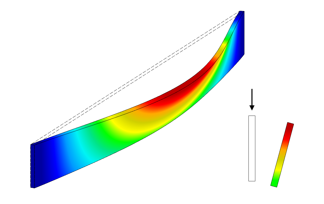
Slender bending beams that have a large h/w ratio and are loaded parallel to the minor axis tend to have stability issues. This is due to the deflection of the compression chord.

The calculation of timber panels is carried out on simplified member or surface structures. This article describes how to determine the required stiffness.

This article explores the importance of considering joint-structure interaction in modeling and design and how to do it in RFEM 6.
In this article, the design of a timber panel wall with the beam panel thickness type is performed.


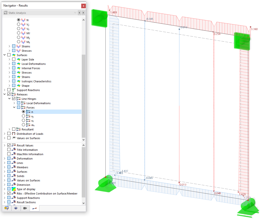
In the RF-LAMINATE add-on module for RFEM, the design of torsional shear stresses in the superposition of net and gross cross-section values is possible. The design is performed separately in the x- and y-directions. The loads on the intersection points of cross-laminated timber panels are checked.

At first, the governing joint designs are arranged in groups and displayed with the basic geometry of the joint in the first result window. In the other result windows, you can see all fundamental design details.
Dimensions, material properties, and welds important for the connection construction are displayed immediately and can be printed directly. Similarly, export to DXF-file is enabled. The connections can be visualized in the RF-/JOINTS Timber - Timber to Timber module as well as in RFEM/RSTAB.
All graphics can be included in the RFEM/RSTAB printout report or printed directly. Due to the scaled output, an optimal visual check is possible as early as in the design phase.

The following design results are displayed:
- Check of minimum spacing
- Load-carrying capacity of each screw
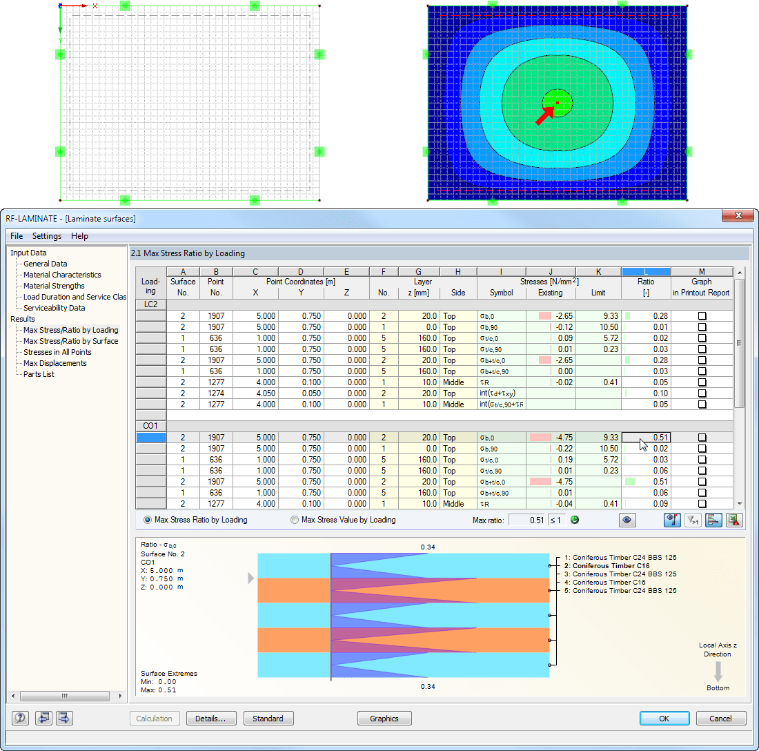
After the calculation, the maximum stresses, stress ratios, and displacements are displayed by load case, surface, or grid points. The design ratio can be related to any kind of stress type. The current location is highlighted by color in the RFEM model.
In addition to the result evaluation in tables, it is possible to display the stresses and stress ratios graphically in the RFEM work window. For this, you can adjust the colors and values assigned in the panel.
Can I change the cutting angle for the "Main member only" joint type?
According to DIN EN 1995‑1‑1/NA, the crack factor kcr may be increased by 30% for softwood in areas that are at least 1.50 m from the timber grain plane. How is it possible to apply this in RF‑/TIMBER Pro?
In the Steel Joints add-on, I get high utilization ratios for preloaded bolts in the tension design. Where do these high utilization ratios come from and how can I evaluate the load-bearing reserves of the bolt?
How can treating a connection as fully rigid result in an uneconomical design?
Is it possible to consider shear panels and rotational restraints in the global calculation?
Do I need to add a line hinge/line release for the CLT wall-to-floor connection in the Building Model add-on?


_1.jpg?mw=350&hash=ab2086621f4e50c8c8fb8f3c211a22bc246e0552)


Recommended Products for You
RFEM 6 | Main Program RFEM 6

The new generation of 3D FEA software is used for the structural analysis of members, surfaces, and solids.
Price of First License
4,790.00 USD
RFEM 6 | Design

The Steel Design add-on performs the ultimate and serviceability limit state design checks of steel members according to various standards.
Price of First License
2,970.00 USD
RFEM 6 | Joints
.png?mw=600&hash=49b6a289915d28aa461360f7308b092631b1446e)
The Steel Joints add-on for RFEM allows you to analyze steel connections using an FE model. The FE model is generated automatically in the background and can be controlled via the simple and familiar input of components.
Price of First License
2,670.00 USD
RFEM 6 | Additional Analysis

The Torsional Warping (7 DOF) add-on allows you to consider cross-section warping as an additional degree of freedom.
Price of First License
1,660.00 USD
RFEM 6 | Additional Analysis

The Nonlinear Material Behavior add-on allows you to consider material nonlinearities in RFEM for example, isotropic plastic, orthotropic plastic, isotropic damage).
Price of First License
1,660.00 USD
RFEM 6 | Additional Analysis

The Structure Stability add-on performs stability analysis of structures. It determines critical load factors and the corresponding stability modes.
Price of First License
1,460.00 USD
RFEM 6 | Additional Analysis

The Construction Stages Analysis (CSA) add-on allows for considering the construction process of structures (member, surface, and solid structures) in RFEM.
Price of First License
1,760.00 USD
RFEM 6 | Additional Analysis

The Time-Dependent Analysis (TDA) add-on allows you to consider the time-dependent material behavior of members and surfaces. The long-term effects, such as creep, shrinkage, and aging, can influence the distribution of internal forces, depending on the structure.
Price of First License
1,160.00 USD
RFEM 6 | Additional Analysis

The Form-Finding add-on finds the optimal shape of members subjected to axial forces and tension-loaded surface models. The shape is determined by the equilibrium between the member axial force or the membrane stress and the existing boundary conditions.
Price of First License
2,320.00 USD
RFEM 6 | Dynamic Analysis

The Modal Analysis add-on allows for the calculation of eigenvalues, natural frequencies, and natural periods for member, surface, and solid models.
Price of First License
1,360.00 USD
RFEM 6 | Dynamic Analysis

Using the Pushover Analysis add-on, you can analyze the seismic actions on a particular building, and thus assess whether the building can withstand an earthquake.
Price of First License
1,460.00 USD
RFEM 6 | Special Solutions

The Building Model add-on for RFEM allows you to define and manipulate a building using stories. The stories can be adjusted in many ways afterwards. The information about stories and the entire model (center of gravity) is displayed in tables and graphics.
Price of First License
1,970.00 USD
RFEM 6 | Design

The Stress-Strain Analysis add-on performs general stress analysis by calculating the existing stresses and comparing them with the limit stresses.
Price of First License
1,360.00 USD
RSTAB 9 | Main Program RSTAB 9

The modern 3D structural analysis and design program is suitable for the structural and dynamic analysis of beam structures as well as the design of concrete, steel, timber, and other materials.
Price of First License
3,380.00 USD
RSTAB 9 | Design
The Steel Design add-on performs the ultimate and serviceability limit state design checks of steel members according to various standards.
Price of First License
2,970.00 USD
RSTAB 9 | Additional Analysis
The Structure Stability add-on performs the stability analysis of structures. It determines critical load factors and the corresponding stability modes.
Price of First License
1,460.00 USD
RSTAB 9 | Design
The Stress-Strain Analysis add-on performs a general stress analysis by calculating the existing stresses and comparing them to the limit stresses.
Price of First License
1,260.00 USD
RSTAB 9 | Additional Analysis
The Torsional Warping (7 DOF) add-on allows for considering cross-section warping as an additional degree of freedom when calculating members.
Price of First License
1,660.00 USD
RSTAB 9 | Dynamic Analysis
The Modal Analysis add-on allows for the calculation of eigenvalues, natural frequencies, and natural periods for member, surface, and solid models.
Price of First License
1,360.00 USD
RSTAB 9 | Dynamic Analysis
Earthquakes may have a significant impact on the deformation behavior of buildings. A pushover analysis allows you to analyze the deformation behavior of buildings and compare them with seismic actions. Using the Pushover Analysis add-on, you can analyze the seismic actions on a particular building, and thus assess whether the building can withstand the earthquake.
Price of First License
1,460.00 USD
RFEM 6 | Design

The Timber Design add-on performs the ultimate, serviceability, and fire resistance limit state design checks of timber members according to various standards.
Price of First License
2,170.00 USD
RSTAB 9 | Design
The Timber Design add-on performs the ultimate, serviceability, and fire resistance limit state design checks of timber members according to various standards.
Price of First License
2,170.00 USD
RX-TIMBER 2 | Timber Structures

Timber design of single-span and wide-span glulam beams according to Eurocode 5 or DIN 1052
Price of First License
1,260.00 USD
RX-TIMBER 2 | Timber Structures

Timber design of simple, continuous, and Gerber beams with or without cantilever according to Eurocode 5 or DIN 1052
Price of First License
400.00 USD
RX-TIMBER 2 | Timber Structures

Timber design of rectangular and circular columns according to Eurocode 5 or DIN 1052
Price of First License
400.00 USD
RX-TIMBER 2 | Timber Structures

Timber design of coupled purlins and continuous beams according to Eurocode 5 or DIN 1052
Price of First License
400.00 USD
RX-TIMBER 2 | Timber Structures

Timber design of three-hinged frames with finger joint connections according to Eurocode 5 or DIN 1052
Price of First License
400.00 USD
RX-TIMBER 2 | Timber Structures

Timber design of stiffening truss bracing according to Eurocode 5 or DIN 1052
Price of First License
400.00 USD
RX-TIMBER 2 | Timber Structures

Timber design of flat, monopitch, and duopitch roofs according to Eurocode 5
Price of First License
400.00 USD
RFEM 6 | Special Solutions

The Multilayer Surfaces add-on allows you to define multilayer surface structures. The calculation can be carried out with or without the shear coupling.
Price of First License
1,560.00 USD
RFEM 6 | Special Solutions

The two-part Optimization & Costs / CO2 Emission Estimation add-on finds suitable parameters for parameterized models and blocks via the artificial intelligence (AI) technique of particle swarm optimization (PSO) for compliance with common optimization criteria. Furthermore, this add-on estimates the model costs or CO2 emissions by specifying unit costs or emissions per material definition for the structural model.
Price of First License
1,660.00 USD
RFEM 6 | Design

The Concrete Design add-on allows for various design checks according to international standards. You can design members, surfaces, and columns, as well as perform punching and deformation analyses.
Price of First License
2,970.00 USD
RFEM 6 | Design

The Masonry Design add-on for RFEM allows you to design masonry using the finite element method. It was developed as part of the research project titled DDMaS – Digitizing the Design of Masonry Structures. The material model represents the nonlinear behavior of the brick-mortar combination in the form of macro-modeling.
Price of First License
1,860.00 USD
RFEM 6 | Design

The Aluminum Design add-on performs the ultimate and serviceability limit state design checks of aluminum members according to various standards.
Price of First License
1,970.00 USD
RSTAB 9 | Special Solutions
The two-part Optimization & Costs / CO2 Emission Estimation add-on finds suitable parameters for parameterized models and blocks via the artificial intelligence (AI) technique of particle swarm optimization (PSO) for compliance with common optimization criteria. Furthermore, this add-on estimates the model costs or CO2 emissions by specifying unit costs or emissions per material definition for the structural model.
Price of First License
1,660.00 USD
RSTAB 9 | Design
Concrete Design add-on allows for various design checks of members and columns according to international standards.
Price of First License
2,970.00 USD
RSTAB 9 | Design
The Aluminum Design add-on performs the ultimate and serviceability limit state design checks of aluminum members according to various standards.
Price of First License
1,970.00 USD
RFEM 6 | Additional Analysis

In RFEM, the Geotechnical Analysis add-on uses properties from soil samples to determine the soil body to be analyzed. The accurate determination of soil conditions significantly affects the quality of the structural analysis of buildings.
Price of First License
1,660.00 USD