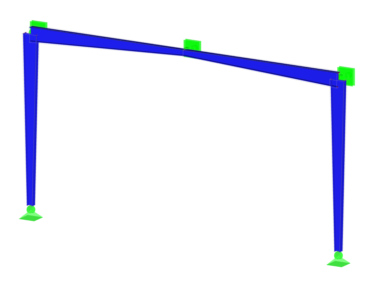
The most common causes of unstable models are failing member nonlinearities such as tension members.
The following model of a frame whose columns are simply supported at the base point and which has moment releases at the column head serves as an example of this.
However, if it is loaded vertically, both tension members fail and the structural system becomes unstable, which causes a calculation error. You can avoid such an error by selecting the exceptional handling of failing members under "Calculate" → "Calculation Parameters" → "Global Calculation Parameters".
Steel Frame Structure
Number of Nodes | 4 |
Number of Members | 5 |
Number of Load Cases | 3 |
Total Weight | 0.668 tons |
Dimensions (Metric) | 5.500 x 0.500 x 5.250 m |
Dimensions (Imperial) | 18.04 x 1.64 x 17.22 feet |
Program Version | 8.04.00 |
You can download this structural model to use it for training purposes or for your projects. However, we do not assume any guarantee or liability for the accuracy or completeness of the model.
![Unstable Model](/en/webimage/010177/3001496/Instabilitaetsmeldung_en.png.png?mw=512&hash=fd797aba7a9f5dda2605369c2aaa4f54213aeffb)
![Frame with Buckling Members](/en/webimage/014935/2952463/000577.png?mw=512&hash=58b9f117858bda66c862b572680da6e125df3b1a)
![KB 001883 | Plate Girder Design According to AISC 360-22 in RFEM 6](/en/webimage/051561/3980997/im1.png?mw=512&hash=b8237709c4f30213fac51d86d32a42bddde72f03)
![Steel Connection Rigidity and Its Influence on Structural Design](/en/webimage/051432/3972404/Rigidity-caseA.png?mw=512&hash=3be64e68ab2956fd2b92f0afa1559b3a8c72b468)
![Add-on "Steel Joints for RFEM 6" | Component Library](/en/webimage/043097/3898884/steel_joints_components.png?mw=512&hash=e4f835906155863fc7019d5043b22e553dc766f9)
- Numerous component types, such as base and end plates, web angles, fin plates, gusset plates, stiffeners, tapers, or ribs for easy input of typical connection situations
- Universally applicable basic components (such as plates, welds, bolts, auxiliary planes) for modeling complex connection situations
- Graphical display of the connection geometry with dynamic updating during the input
- Wide range of cross-section shapes: I-sections, U-sections, angles, T-sections, hollow sections, built-up cross-sections and thin-walled sections
- Library in the Dlubal Center with a large number of program-side template connections, including user-defined templates
- Automatic adaptation of the connection geometry based on the relative arrangement of the components to each other – even in case of subsequent editing of the structural components
![Feature 002820 | Limit Plastic Strain for Welds](/en/webimage/050344/3881226/1.png?mw=512&hash=9d7f6c198b6d4ae6ee8f2fa8bca75f85579e14c9)
In the ultimate configuration of the steel joint design, you have the option to modify the limit plastic strain for welds.
![Component "Base Plate"](/en/webimage/050345/3936120/50345.png?mw=512&hash=3bd641cb1a2445804b338855e4debfc40c6563e9)
The "Base Plate" component allows you to design base plate connections with cast-in anchors. In this case, plates, welds, anchorages, and steel-concrete interaction are analyzed.
![Feature 002807 | 3D Display of FSM Results](/en/webimage/049281/3861162/2024-05-01_10-32-55.png?mw=512&hash=2377d291bc20ac3d78d617b50c131614e99ac6f7)
In the "Edit Section" dialog box, you can display the buckling shapes of the Finite Strip Method (FSM) as a 3D graphic.