In EN 1993-1-1, the General Method was introduced as a design format for stability analyses that can be applied to planar systems with arbitrary boundary conditions and variable structural height. The design checks can be performed for loading in the main load-bearing plane and simultaneous compression. The stability cases of lateral-torsional buckling and flexural buckling are analyzed from the main supporting plane; that is, about the weak component axis. This model was used to explain the question of how flexural buckling in the main supporting plane can be verified in this context.
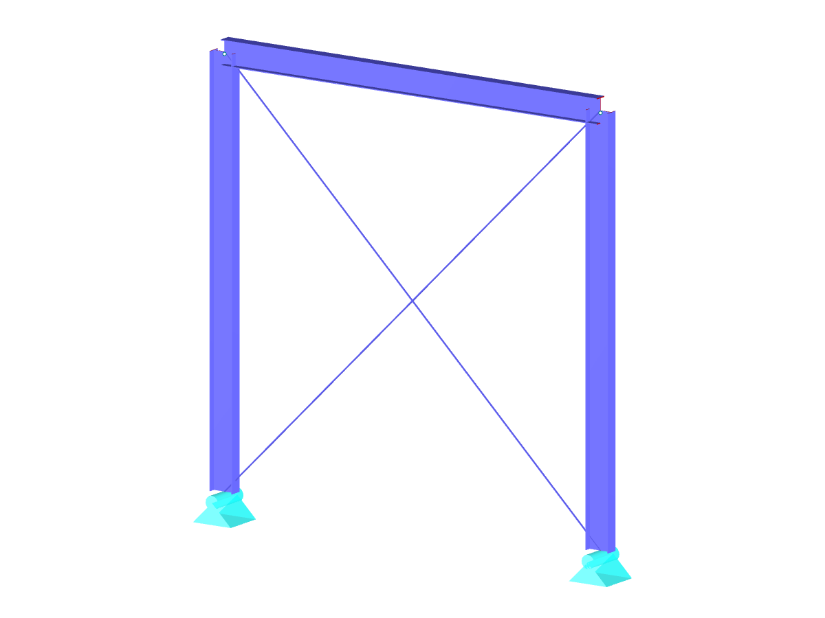
Tapered Steel Frame Structure
Number of Nodes | 5 |
Number of Lines | 4 |
Number of Members | 4 |
Number of Load Cases | 4 |
Number of Load Combinations | 3 |
Total Weight | 1.734 tons |
Dimensions (Metric) | 12.600 x 0.600 x 6.750 m |
Dimensions (Imperial) | 41.34 x 1.97 x 22.15 feet |
Program Version | 5.23.02 |
You can download this structural model to use it for training purposes or for your projects. However, we do not assume any guarantee or liability for the accuracy or completeness of the model.
![Smallest Magnification Factor for Flexural Buckling in Frame Plane](/en/webimage/010280/2993348/1_mode_shape_in_plane_buckling.png?mw=512&hash=3ae4b5e831c1025605c328fda1a888e0a3d36055)
![Structural System and Loading](/en/webimage/009829/2420634/01-en-png-png.png?mw=512&hash=6ca63b32e8ca5da057de21c4f204d41103e6fe20)
![System](/en/webimage/009546/2419321/01-en-png.png?mw=512&hash=e5b08a40fd9a5a16825be6182b3138f78627561e)
![Design Loads and Imperfections for Structural Analysis](/en/webimage/011704/2599265/1626-5-en-us-png.png?mw=512&hash=fa62f0f4ca3d0d5ad78f02510d0c0f076500e2b9)
![Add-on "Steel Joints for RFEM 6" | Component Library](/en/webimage/043097/3898884/steel_joints_components.png?mw=512&hash=e4f835906155863fc7019d5043b22e553dc766f9)
- Numerous component types, such as base and end plates, web angles, fin plates, gusset plates, stiffeners, tapers, or ribs for easy input of typical connection situations
- Universally applicable basic components (such as plates, welds, bolts, auxiliary planes) for modeling complex connection situations
- Graphical display of the connection geometry with dynamic updating during the input
- Wide range of cross-section shapes: I-sections, U-sections, angles, T-sections, hollow sections, built-up cross-sections and thin-walled sections
- Library in the Dlubal Center with a large number of program-side template connections, including user-defined templates
- Automatic adaptation of the connection geometry based on the relative arrangement of the components to each other – even in case of subsequent editing of the structural components
![Feature 002820 | Limit Plastic Strain for Welds](/en/webimage/050344/3881226/1.png?mw=512&hash=9d7f6c198b6d4ae6ee8f2fa8bca75f85579e14c9)
In the ultimate configuration of the steel joint design, you have the option to modify the limit plastic strain for welds.
![Component "Base Plate"](/en/webimage/050345/3936120/50345.png?mw=512&hash=3bd641cb1a2445804b338855e4debfc40c6563e9)
The "Base Plate" component allows you to design base plate connections with cast-in anchors. In this case, plates, welds, anchorages, and steel-concrete interaction are analyzed.
![Feature 002807 | 3D Display of FSM Results](/en/webimage/049281/3861162/2024-05-01_10-32-55.png?mw=512&hash=2377d291bc20ac3d78d617b50c131614e99ac6f7)
In the "Edit Section" dialog box, you can display the buckling shapes of the Finite Strip Method (FSM) as a 3D graphic.